
Amplifier Timer

This circuit is designed to manage the operational state of an amplifier or similar device based on the presence of an audio signal. The core components include operational amplifiers, a timer IC, transistors, and a relay, which work together to achieve the desired functionality.
The circuit begins with an audio input, which is processed by operational amplifiers IC2A and IC2B. These components amplify the low-level audio signal and convert it into a square wave, facilitating easier detection of the signal's presence. The output of the second operational amplifier feeds into an LED indicator (D4), which visually indicates the presence of the audio signal.
The timer IC (IC3) plays a crucial role in monitoring the duration of the audio signal's absence. Initially, when an audio signal is detected, D4 illuminates, which resets the timer, preventing it from counting down. The timer's output at pin 2 remains low, which keeps the connected transistors in an "on" state, allowing current to flow through the relay. This operation ensures that the connected appliance, via connector SK1, remains powered.
If the audio signal is absent for 15 minutes, the timer completes its countdown, and pin 2 transitions to a high state. This change turns off the transistors, deactivating the relay and consequently cutting power to the appliance.
The circuit is equipped with a manual override switch (P1), allowing the user to turn on the device regardless of the audio signal state. This feature provides flexibility for scenarios where immediate operation is required without waiting for the audio signal to be detected.
Overall, this circuit effectively manages power consumption by turning off devices during periods of inactivity, thus contributing to energy efficiency. The use of visual indicators and manual controls enhances user interaction and operational reliability.This circuit turns-off an amplifier or any other device when a low level audio signal fed to its input is absent for 15 minutes at least. Pushing P1 the device is switched-on feeding any appliance connected to SK1. Input audio signal is boosted and squared by IC2A & IC2B and monitored by LED D4. When D4 illuminates, albeit for a very short peak, IC3 is reset and restarts its counting. Pin 2 of IC3 remains in the low state, the two transistors are on and the relay operates. When, after a 15 minutes delay, no signal appeared at the input, IC3 ends its counting and pin 2 goes high.
🔗 External reference
Related Circuits
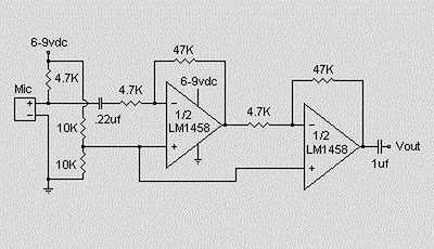
This circuit utilizes an LM1458 dual operational amplifier integrated circuit (IC) to amplify audio signals from a condenser microphone. The amplified output allows the microphone to interface with devices that typically do not accept microphone-level signals. The circuit operates...
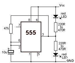
This LED flasher circuit utilizes the 555 timer integrated circuit (IC). The circuit diagram is straightforward and requires only a few external components. When operational, the red LEDs will flash sequentially at a predetermined frequency, similar to the indicators...
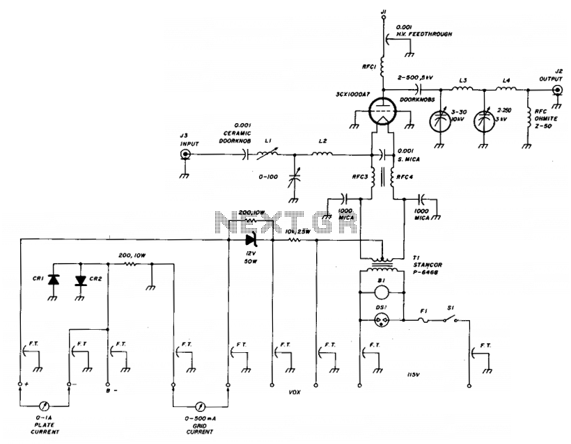
The amplifier utilizes a grounded grid circuit featuring either the Eimac 3CX1000A7 or 8877 ceramic/metal triodes designed for linear operation within the HF and VHF frequency ranges. It delivers a legal power output of 1500 watts PEP and continuous...
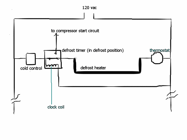
The location of the defrost timer in a refrigerator varies based on the manufacturer and model. In some refrigerators, the defrost timer can be found at the rear near the compressor, while in others, it is located behind the...
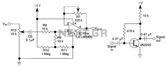
This circuit utilizes one-quarter of an LM3900 to create a simple variable-gain front end for an oscilloscope. R7 serves as the gain control. Additionally, a basic preamplifier is included for applications requiring more than 10X gain. The circuit employs the...
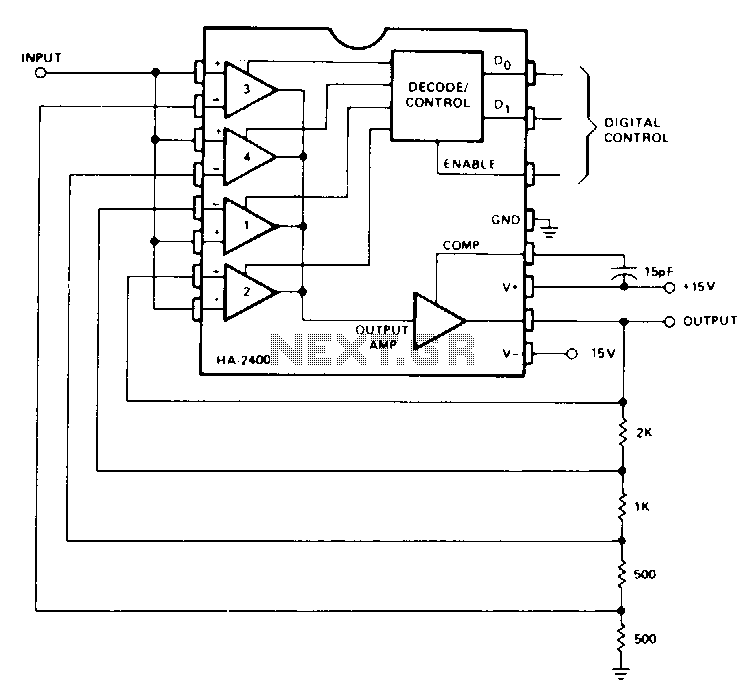
This is a non-inverting amplifier configuration with feedback resistors selected to achieve a gain of 0, 1, 2, 4, or 8, based on digital control inputs. Comparators at the output may be utilized for automatic gain selection in applications...