555 timer Led Flasher circuit electronic project
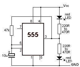
This LED flasher circuit utilizes the 555 timer integrated circuit (IC). The circuit diagram is straightforward and requires only a few external components. When operational, the red LEDs will flash sequentially at a predetermined frequency, similar to the indicators used at railway crossings.
The LED flasher circuit based on the 555 timer IC operates in astable mode, allowing it to generate a continuous square wave output. This configuration is ideal for creating a flashing effect with LEDs. The primary components involved in this circuit include the 555 timer IC, resistors, capacitors, and the red LEDs.
The 555 timer is connected in an astable configuration, where it alternates between its high and low states. The frequency of the flashing can be adjusted by varying the resistor and capacitor values connected to the timer. Typically, two resistors (R1 and R2) and one capacitor (C1) are used to set the timing intervals. The formula for calculating the frequency (f) of the output signal is given by:
f = 1.44 / ((R1 + 2 * R2) * C1)
In this arrangement, R1 connects to the discharge pin (pin 7) and the threshold pin (pin 6), while R2 connects to the threshold pin and the trigger pin (pin 2). The capacitor C1 is connected between the threshold pin and ground. This configuration allows the capacitor to charge and discharge, thus creating the oscillation required for the LED flashing.
The output from the 555 timer is fed into the anodes of the red LEDs, with the cathodes connected to ground. To achieve the sequential flashing effect, additional components such as a shift register or a simple transistor driver circuit may be implemented. These components can control the individual LEDs, ensuring they light up one after the other in a synchronized manner.
Powering the circuit typically requires a DC voltage supply, which can range from 5V to 15V, depending on the specifications of the 555 timer and the LEDs used. Proper heat dissipation and current limiting resistors for the LEDs should also be considered to prevent damage.
This LED flasher circuit is not only simple to construct but also serves as an excellent project for understanding the functionality of the 555 timer IC and basic electronic principles.This LED Flasher circuit is based on the 555 timer IC. The LED Flasher circuit diagram is very simple and require few external components. When the circuit is working the red LEDs will flash at a set frequency one by one like at the railway crossing indicator. 🔗 External reference
