
An Efficient Low-Power Arduino Switching Voltage Regulator

The Texas Instruments MC33063A is a versatile DC/DC converter capable of performing various voltage regulation tasks. When configured as a buck regulator, it efficiently steps down the voltage from a higher level, which is essential for powering low-voltage devices like microcontrollers and wireless modules. The circuit typically includes external components such as inductors, diodes, and capacitors, which are crucial for smoothing the output voltage and ensuring stable operation.
In this design, the selection of resistor values R1 and R2 is critical for determining the output voltage. The formula used to calculate the output voltage (Vout) in a buck configuration is given by:
\[ V_{out} = V_{ref} \times \left(1 + \frac{R2}{R1}\right) \]
where \( V_{ref} \) is the reference voltage of the MC33063A, typically around 1.25V. By choosing R1 = 100 kOhm and R2 = 200 kOhm, the output voltage is adjusted to approximately 3.75V, which is suitable for the ATmega328 microcontroller and the XBee radio module, ensuring reliable operation.
The efficiency of this switching regulator is markedly higher than that of linear regulators, as it minimizes power loss by converting excess voltage into usable current rather than dissipating it as heat. This results in lower current consumption, particularly when the load is minimal, thereby prolonging battery life significantly.
In summary, the implementation of the MC33063A as a buck regulator not only enhances the efficiency of the power supply for the Arduino and associated components but also extends the operational lifespan of the battery, making it an ideal choice for portable, battery-operated projects.The voltage regulator built onto the Arduino Uno is a linear-type regulator and is horribly inefficient. If you are running the ATmega238 at 5V using a 9 V battery, approximately half of the battery`s energy will be dissipated as heat by the regulator.
This post demonstrates a DC/DC switching-type voltage regulator circuit that can be use with a b readboard Arduino and is much more efficient then a typical 7805 regulator. The switching regulator used is a Texas Instruments MC33063A. This IC can be used with external components to make a boost regulator (to step up voltage), a buck regulator (to step down voltage), or an inverting regulator. Here I am setting it up as a buck regulator to step down a 12 V battery pack to run a 3. 3 V breadboard Arduino and XBee radio. Here is the voltage regulator circuit schematic. In my design, I am using R1 = 100 kOhm and R2 = 200 kOhm giving me an output voltage of approximately 3.
75 V to power both an ATMega328 and an XBee Series 1 radio. Depending on the values of R1 and R2, this switching regulator circuit uses about 2. 5 to 3. 5 mA of current when not powering a load. This compares to about 10 15 mA for a 7895 linear regulator. By using this regulator circuit design, my battery lasts for almost two weeks. 🔗 External reference
Related Circuits
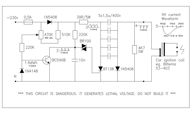
This circuit generates high voltage pulses from a 230 VAC line voltage. The drive end's swing comparator circuit was developed by the creator of this page. The working end is derived from a stroboscope trigger supply circuit. All circuits...
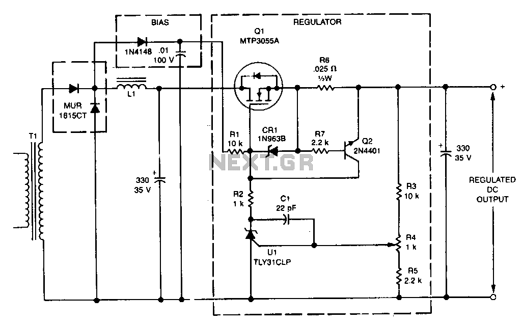
This linear post regulator provides 12 V at 3 A. It utilizes the TL431 reference (U1), which, without additional amplification, drives the gate of the TMOS MTP3055A (Q1) series pass regulator. A bias voltage is applied through resistor R1...
In electronic technology, the triode utilizes a variety of general components and parts. The parameters of the triode and numerous electrical parametric measurement schemes are closely related to measurement results. Therefore, in electronic design, the base pin, typological judgment,...
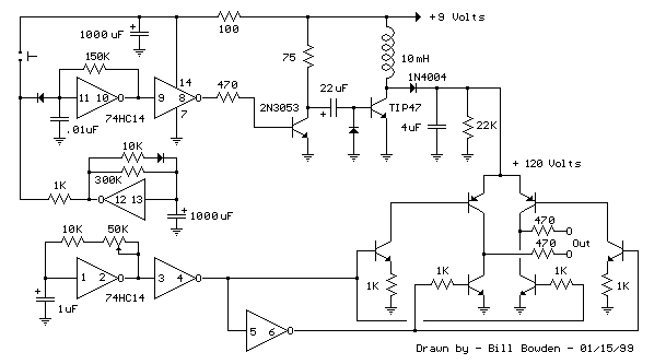
The telephone ring generator described generates the necessary aerial voltage using a simple switched-mode power supply (SMPS). It incorporates a CMOS Schmitt Trigger-based oscillator, a 10 mH inductor, a high-voltage switching transistor (such as the TIP47 or another high-voltage,...
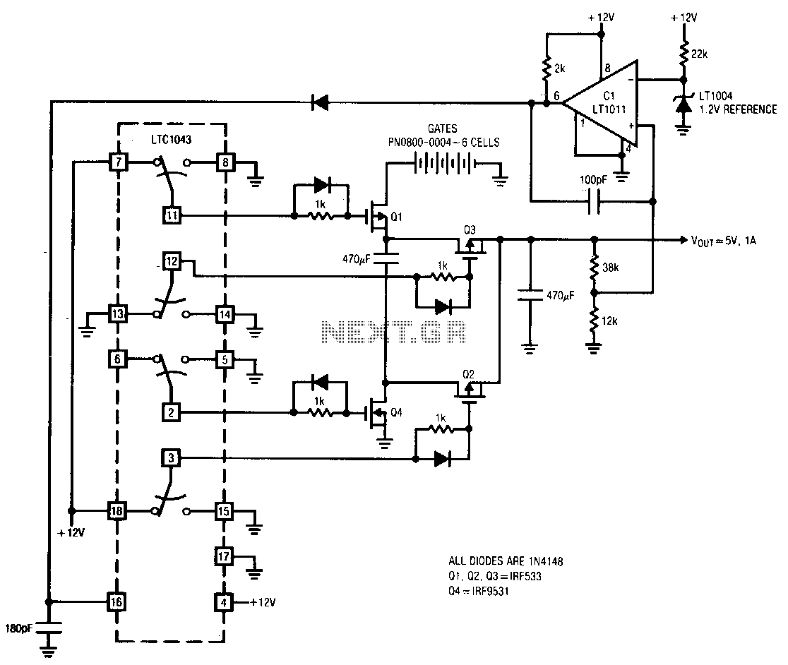
The LTC10432 switched-capacitor building block provides non-overlapping complementary drive to the Q1 to Q4 power MOSFETs. The MOSFETs are arranged such that C1 and C2 are alternately placed in series and parallel configurations. During the series phase, the +12...
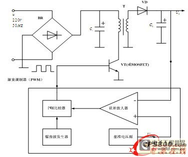
The energy conservation provided by switching power supplies has garnered significant attention due to its substantial economic benefits, leading to rapid adoption across various sectors. With the swift advancement in power technology, high-frequency operation has become a prevailing trend...