
High Voltage Pulse Generator Electronic Circuit

This circuit utilizes a high-voltage pulse generation mechanism, which is critical in applications requiring intense energy discharge. The primary component, a swing comparator circuit, operates by comparing input voltages and generating a controlled output that can drive a high-voltage transformer or coil. The design is based on a stroboscope trigger supply, which is known for its rapid pulsing capabilities, making it suitable for applications that demand precise timing and high energy.
The high-voltage output is capable of producing arcs up to 25 mm in length, indicative of the energy levels involved. The measurement of output current is performed by connecting a 10-ohm resistor in series with the output, allowing for the calculation of current through voltage drop observations using an oscilloscope. This method provides real-time feedback on the circuit's performance and allows for adjustments to be made to optimize the operation.
The control of the triggering event is achieved through a 470K potentiometer, which allows for fine-tuning of the phase angle between 180 and 270 degrees. This range is critical for ensuring that the output pulses are synchronized with the AC line frequency, thus maximizing the efficiency of the energy transfer.
Due to the high voltages and the nature of the circuit, safety precautions are paramount. The circuit should only be handled by individuals with appropriate expertise in high-voltage systems, and proper protective equipment should be used at all times. The circuit's design and operation highlight the importance of understanding the risks associated with high-voltage electronics, particularly in terms of potential electrical hazards and fire risks, as illustrated by the immediate ignition of paper placed near the arc.This circuit generates high voltage pulses from 230vac line voltage. The drive end`s swing comparator circuit is invented by the creator of this page. The work end is derived from stroboscope trig supply circuit. All line voltage using circuits are inherently dangerous, and this is particulary so. Do not build it. When powered up, the circuit gene rated fierce arc of 25mm length, between the coil secondary. The waveforms depicted in the schematic were observed. The output current was measured by letting the sparks ground via a 10ohm resistor, and measuring the voltage over the resistor with an oscilloscope. The trig event control was observed between ca. 180. 270 degrees of phase angle, by turning the 470K potentiometer. The sheet of paper placed between arc bursted immediately in flames. 🔗 External reference
Related Circuits
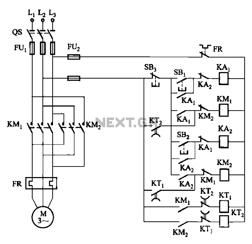
The circuit depicted in Figure 3-131 utilizes a relay instead of a speed control relay. It is designed to operate effectively in dusty environments and other challenging conditions. The circuit operates by employing a relay as a primary switching mechanism,...

Early in the exploration of high-power LEDs, such as the Luxeon 1 and 3-watt devices, the potential of Pulse Width Modulation (PWM) techniques for LED modulation was considered. This method theoretically minimizes distortion by making the LED's "Current versus...

The circuit activates a light corresponding to the first button pressed in a "Who's First" game. Three stages are illustrated, but the circuit can be expanded to accommodate any number of buttons and lamps. The described circuit operates as a...
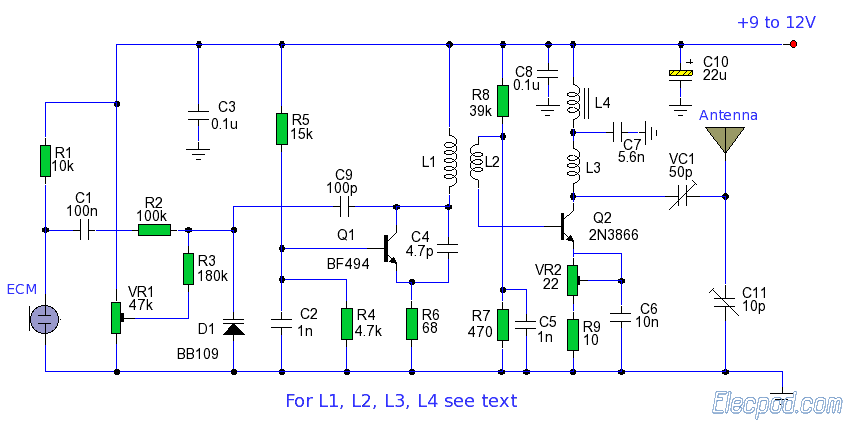
The ZN414 is an economical, single-chip AM radio integrated circuit introduced in 1972 by Ferranti. The TDA7000 is a monolithic integrated circuit designed for mono FM portable radios or receivers, focusing on minimizing size. Additionally, there is an FM...
XP power plug, FU fuse, ST temperature control, T1 low-voltage transformers, S1, S2 door interlock switch, S3 threshold control switch, RT thermal sensor, K1, K2 relay, EL furnace light, M1 wheel motor, M2 fan motor, T2 high-voltage transformer, C...
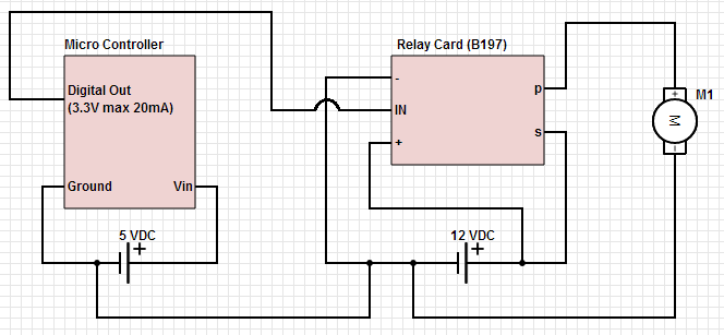
The objective is to control a 12 VDC device (on/off) from a microcontroller using a relay card. The relay requires a 12 VDC operating power supply. To achieve the control of a 12 VDC device using a microcontroller and a...