
The low-powered BJT base pin cast differentiates the circuit cipher scheme automatically

The described automatic base pin differentiation circuit for triodes is a sophisticated design that streamlines the measurement process for these essential electronic components. The use of the AT89C2051 microcontroller as the central control unit allows for efficient processing and management of the measurement data. The integration of various components such as the CD4069 inverter and optocouplers enhances the circuit's ability to accurately detect and interpret the electrical characteristics of different triode types. This not only simplifies the measurement procedure but also increases reliability and accuracy, which is critical in electronic design and testing environments. Furthermore, the display circuit provides a clear visual indication of the triode type, facilitating quick identification and assessment by engineers and technicians. Overall, this circuit design represents a significant advancement in the automated measurement and classification of triodes, addressing existing challenges and improving workflow efficiency in electronic laboratories.In electron technology, the triode uses a kind of extremely general components and parts, the parameter of the triode and a lot of electricity parametric measurement schemes, measuring results have a very close relation, so, in the electronic design, the base pin, typological judgement and measurement of the triode are very important. Measuring the base pin method of the triode has multi-type, among them a commonly used one of laboratory is that the use multimeter and characteristic of triode every base pin carry on measurement, but because the voltage, electric current relation among each pin of the triode are complicated, and triode own volume minor, bring to measurement greatly inconvenient, at present at the market yet to the intersection of triode and base pin, device that type differentiates automatically. So, designing one seem particularly important to can differentiate the base pin of the triode, typological circuit automatically.
Arrange the way according to type and base pin of the daily triode at present, the ones that designed differentiated the circuit automatically and included central control unit, chance-over circuit, measured the amplifying circuit and four parts of display circuit, as shown in Fig. 1, among them use AT89C2051 as the central control unit. Fig. 2 shows and differentiates the schematic circuit diagram of the hardware automatically for the base pin type of the triode, this hardware circuit mainly includes the one-chip computer AT89C2051, components and parts such as inverter CD4069, photoelectric coupler 4N25, 74LS06, 74LS07, several resistance and electric capacity, etc.
Sent three binary codes different level of level P3. 2 mouth by P3. 0 of the one-chip computer at first, Send to pin No. 1, 2, 3 of the triode separately. As to different triodes, while sending different codes with one-chip computer, current directions on its pin No. 1, 2, 3 are different, have, flow into and flow out two situation, take two serials of photoelectric coupler, have passing of current at how many directions does it come on, find in parallel while being reverse, three binary codes are turned into six binary codes at this moment.
Amplify the detected electric signal from photoelectric coupler, because the signal that outputs at this moment is not the canonial level level, can`t direct the intersection of sheet and slices of machine discern phase place fulfil requirements either, so add the first class inverter CD4069 and go on the oppisite phase, then send six canonial binary codes that the inverter output to P1. 0 P1. 5 mouth of the one-chip computer. The one-chip computer compares with data of the load in advance within the one-chip computer according to the data read out from P1 mouth, output and measure the result from P3.
3 to P3. 7 mouth when meeting the corresponding condition, reveal the correspondent triode type with luminescent diode finally. In electron technology, the triode uses a kind of extremely general components and parts, the parameter of the triode and a lot of electricity parametric measurement schemes, measuring results have a very close relation, so, in the electronic design, the base pin, typological judgement and measurement of the triode are very important.
Measuring the base pin method of the triode has multi-type, among them a commonly used one of laboratory is that the use multimeter and characteristic of triode every base pin carry on measurement, but because the voltage, electric current relation among each pin of the triode are complicated, and triode own volume minor, bring to measurement greatly inconvenient, at present at the market yet to the intersection of triode and base pin, device that type differentiates automatically. So, designing one seem particularly important to can differentiate the base pin of the triode, typological circuit automatically.
Arrange the way according to type and base pin of the daily triode 🔗 External reference
Related Circuits
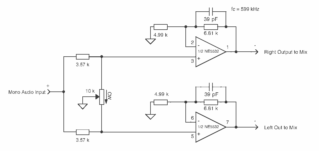
The output voltage is = 0.707 x Vin, at the center position. The output voltage is = Vin, at either extreme position. This circuit appears to describe a variable output voltage system, likely utilizing a potentiometer or a similar adjustable...
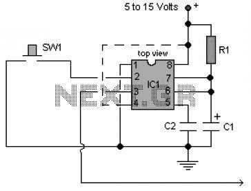
A multivibrator is an electronic circuit used to implement a variety of simple two-state systems such as light-emitting diodes, timers, and flip-flops. The monostable multivibrator will create a condition in which one of the states is stable. A multivibrator circuit...
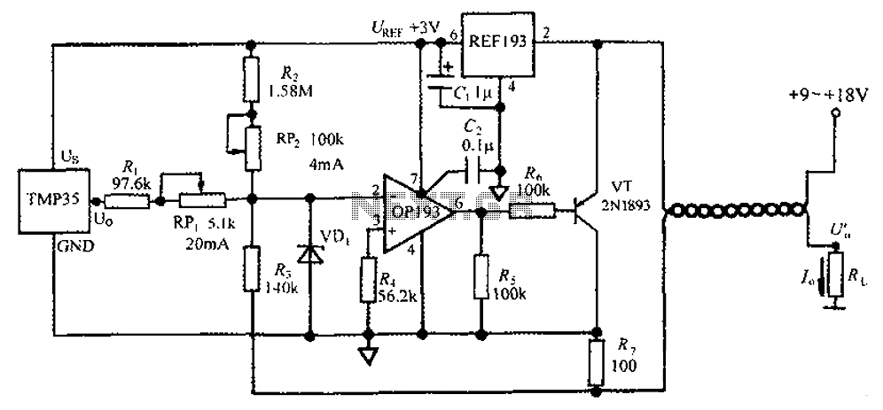
The circuit consists of a TMP35 temperature transmitter that converts a voltage signal output from the TMP35 into a standard 4 to 20 mA current signal. This configuration is suitable for use in automated instrumentation and industrial temperature control...
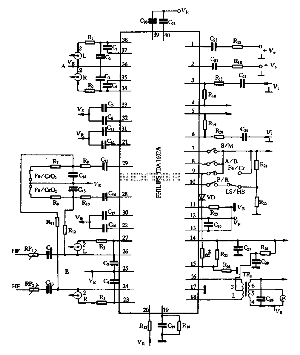
The A1602A is a 40-pin dual in-line package that functions as a playback preamplifier. It utilizes linear low-noise amplifiers with a voltage gain of 26.4 dB. Each channel has a separate discharge sound preamplifier, selected by an electronic switch...
A programmable code lock can be used for numerous applications in which access to an article/gadget is to be restricted to a limited number of persons. Here is yet another circuit of a code lock employing mainly the CMOS...
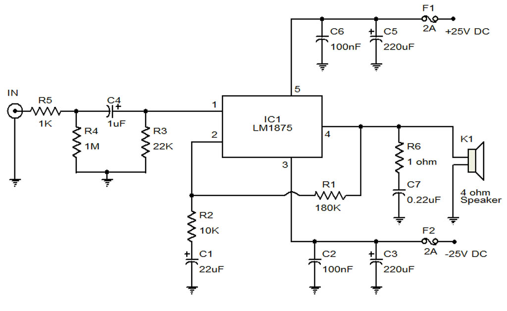
The circuit illustrates a 20-Watt audio amplifier diagram based on the LM1875 integrated circuit (IC). It is designed for use in automotive applications and provides an output power of 20 Watts. The 20-Watt audio amplifier circuit utilizing the LM1875 IC...