
An induction motor dynamic braking control circuit

The circuit utilizes an AC contactor to manage the operation of suction units, integrating a thyristor (SCR) for effective control of the motor's operation. The contactor's primary function is to switch the motor on and off, ensuring that the suction units operate efficiently. When the motor is activated, the contacts CJ1 create a short circuit across the SCR, effectively turning it off to prevent unintended current flow.
During the positive half of the AC waveform, the SCR is triggered through a series of components, including resistors and diodes, which provide the necessary gate current for conduction. The motor receives power through its b and c-phase windings, with contact CJ2 supplying a half-rectified current that supports the motor's operation. The SCR also plays a vital role in delivering bi-directional wave current, which is essential for maintaining the suction units' functionality.
As the positive half-cycle concludes, the induced back EMF in the b and c-phase windings activates the normally closed contact D4, allowing for a freewheeling path that ensures continuity of operation until the next half-cycle. This design prevents abrupt changes in current, contributing to the stability of the system.
The SCR is re-triggered at the onset of the next positive half-cycle, maintaining the current flow through the windings without interruption. The circuit is designed to manage energy efficiently, with charge storage mechanisms in place that allow for dynamic braking when necessary. This braking system minimizes mechanical wear and enhances the longevity of the motor.
Overall, the design emphasizes reliable operation and energy efficiency, utilizing the principles of AC control and SCR technology to achieve effective motor management in the context of suction units. The circuit is structured to ensure safe operation, with considerations for both dynamic braking and the prevention of undesired SCR exclusion under normal operating conditions.AC contactor Cli suction units, motor was switched on at the same time, CJ1 pair of contacts to the thyristor SCR shorted SCR it off. Contactor C interesting by the diode DC vo ltage and suction units, make energy system moving like love. In the positive half-wave power, SCR control electrode through R, W. C, Dl get trigger current conduction through, motor b, c-phase winding through the SCR, CJ2 contacts is to give a half rectified current, C is also provided by SCR BI wave current to maintain suction units. When the end of the positive half-wave current, b. c-phase winding fork induced electric boat, the D4. cl normally closed contact freewheeling. Sentenced next positive half cycle. SCR is turned on again. b, c-phase winding half do not have to fork crossing the current, past through the next cycle, c charge storage charges, SCR trigger current of less than bottles instead guide ila, complete small dynamic braking.
CJ, the power is not released, the SCR again through the small possibility of exclusion.
Related Circuits

To invoke the Spectrum +3 diagnostic routines, first reset the machine while holding the BREAK key down. This will bring up the test card display. Next, hold down the QAZMLP keys for a few seconds until the diagnostic title...
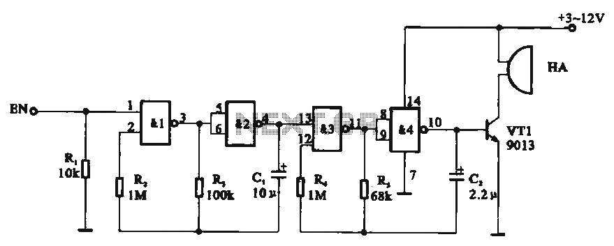
Tone generator circuit. The tone generator circuit utilizes a quad 2-input NAND gate integrated circuit, specifically the CD4011. NAND gates 1 and 2, along with NAND gates 3 and 4, form two gating multivibrator oscillators. The oscillation period of...
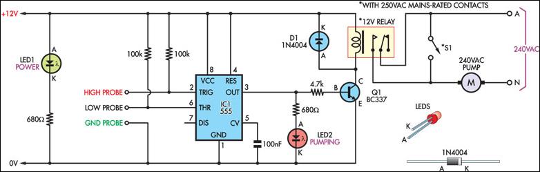
This straightforward yet efficient circuit is designed to manage the water level in a container. The prototype is utilized to pump water out of a bucket that collects condensation from a home air-conditioning system. The design revolves around a...
Atmel Flash devices are well-suited for development due to their ease and speed of reprogramming. They provide ample code space for applications, especially for projects involving the 89Cxx series with the C programming language. Atmel offers a wide selection...
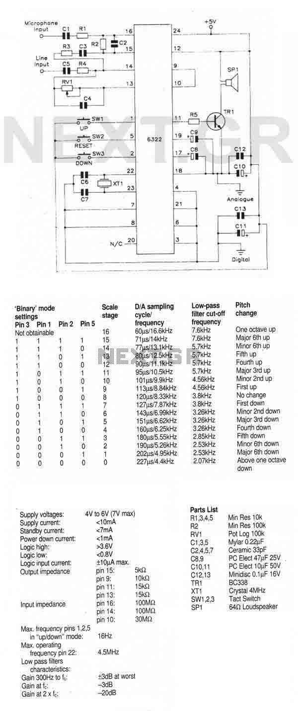
The circuit utilizes the MSM6322GSK, which is available in a compact 24-pin plastic SOP package. This integrated circuit (IC) functions as a real-time speech pitch converter and requires minimal external components. It includes a microphone preamplifier and a line-level...
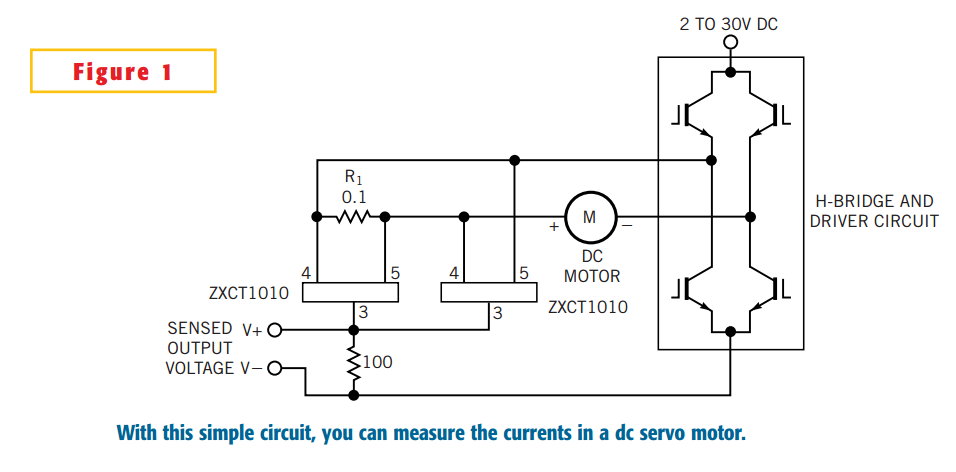
The simple circuit design in Figure 1 lets you measure all components of a current flowing in a dc servo motor. The rectified output of the circuit uses ground as a reference, so you can measure the output by...