
Tone generator circuit
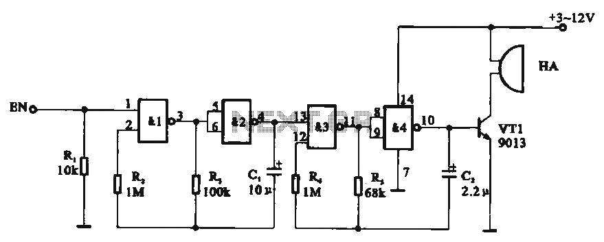
The tone generator circuit is designed around the CD4011 quad 2-input NAND gate integrated circuit. This IC contains four independent NAND gates, which can be configured to create multivibrator circuits. In this specific application, two of the NAND gates are configured as astable multivibrators, producing square wave outputs at different frequencies. The first multivibrator, formed by NAND gates 1 and 2, has a longer period of 2 seconds, while the second multivibrator, formed by NAND gates 3 and 4, oscillates at a much higher frequency of 330 milliseconds.
The output of the first multivibrator serves as a control signal for the second multivibrator. This cascading configuration allows for the modulation of the second oscillator based on the state of the first. The control terminal, labeled EN, plays a critical role in the circuit's operation. When the EN pin is not supplied with a control voltage, the circuit remains inactive, halting any oscillation and producing no sound. However, when a positive voltage is applied to the EN pin, it enables the first multivibrator, which in turn activates the second multivibrator.
The output from the fourth NAND gate generates a series of positive pulses that correspond to the oscillation of the second multivibrator. These pulses are then used to drive an audio output device, such as a buzzer. The resulting sound is characterized by a series of intermittent tones, described as "drip, drip, clear," which can be utilized in various applications requiring sound generation, such as alarms, timers, or notification systems. This design effectively demonstrates the versatility and functionality of NAND gates in creating sound-generating circuits.Tone generator circuit Tone generator circuit shown in FIG. Circuit uses a quad 2-input NAND gate integrated circuit CD4011. NAND gate NAND gate 1,2 and 3,4 form two gating multivibrator oscillation period of the former 2s, the latter oscillation period of 330 ms, and the latter controlled by the output of the former, while the former also by control terminal EN potential control. When the EN pin no control voltage, circuit stop vibration HA no sound issue; when EN end when there is a positive control voltage start-up circuit, the role of the two multivibrators, so the output of NAND gate 4 @ pin output every three positive pulse for a group of intermittent square wave, driven by vri buzzer (Xiangqi) HA issued a "drip, drip, clear" crisp tone.
Related Circuits
Electronics tutorial about the monostable multivibrator circuit, also known as a one-shot monostable multivibrator, used as a pulse generator circuit. The monostable multivibrator is a crucial component in electronic circuits, functioning as a pulse generator that produces a single output...
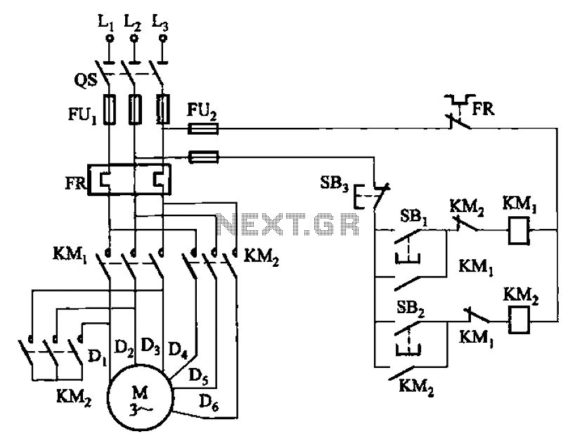
The circuit illustrated in Figure 3-97 features two contacts and is designed specifically for a 2kW dual-speed motor. In this configuration, SB1 is utilized for low-speed operation, while SB2 serves as the high-speed run button. The circuit operates by allowing...
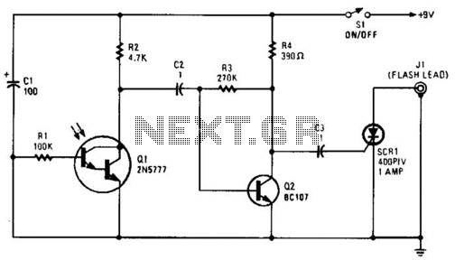
The phototransistor Q1 receives a light pulse from a photoflash unit. The pulse is AC-coupled to amplifier Q2, which subsequently triggers SCR1, activating a flash unit connected to J1. The circuit begins with the phototransistor Q1, which is sensitive to...
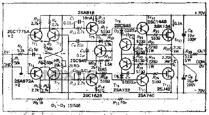
The south circuit consists of four parts, arranged in descending order: an NPN transistor dynamic garbage device (T1), a PNP transistor differential amplifier (T2, T3) forming a double differential circuit, two balanced output amplifiers with opposite phase, and a...
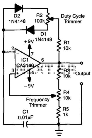
This relaxation oscillator circuit utilizes diodes to create charge and discharge paths for capacitor CI. The duty cycle is determined by resistor R2, while the frequency is controlled by resistor R4. The value of capacitor CI can be adjusted...
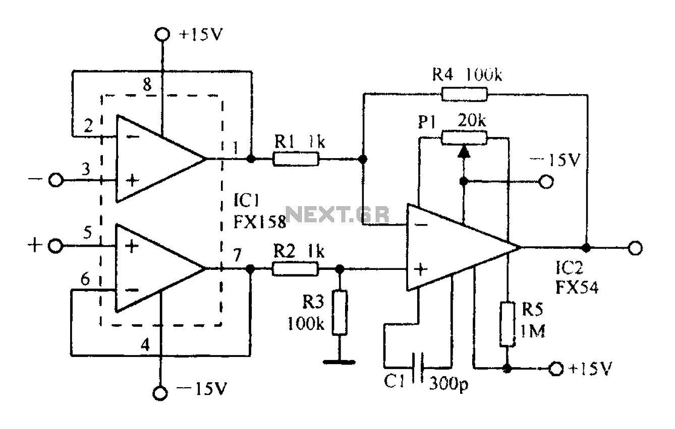
A differential amplifier with input impedance as indicated in the circuit diagram. A differential amplifier is a crucial component in various electronic applications, primarily used to amplify the difference between two input voltages while rejecting any common-mode signals. This characteristic...