
Circuit measures currents in dc servo motor

The described circuit is designed for precise current measurement in a DC servo motor application. The use of a current-sense resistor, R1, valued at 0.1 ohms, is critical for developing a voltage drop proportional to the current flowing through the motor. This voltage drop is then processed by the Zetex ZXCT1010 integrated circuit, which is specifically designed for current sensing applications.
The ZXCT1010 operates by taking the differential voltage across the current-sense resistor and converting it into a single-ended output. This functionality is essential because it simplifies the interfacing of the circuit with a single-ended Analog-to-Digital (A/D) converter, allowing for easier integration into microcontroller systems or digital signal processors. The dual configuration of the ZXCT1010 ICs serves as a signal rectifier, ensuring that the output signal is suitable for accurate measurement.
The design leverages the ground as a reference point, which is a common practice in electronic measurement systems. This approach minimizes the complexity of the circuit and reduces the number of required components. The overall design is optimized for cost, size, and power efficiency, making it ideal for applications where space and energy resources are limited.
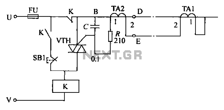
In summary, this circuit design provides a robust solution for measuring current in DC servo motors, utilizing the ZXCT1010 IC for effective signal conversion and ensuring compatibility with single-ended A/D converters. The choice of a low-value current-sense resistor enhances the circuit's sensitivity while maintaining a compact footprint, suitable for various electronic applications.The simple circuit design in Figure 1 lets you measure all components of a current flowing in a dc servo motor. The rectified output of the circuit uses ground as a reference, so you can measure the output by using a single-ended A/D converter.
The current-sense resistor, R1, has a value of 0.1. The Zetex (www.zetex.com) ZXCT1010 IC converts the differential signal across R1 to a single-ended signal. Two of these ICs form a signal rectifier. The single-ended signal makes measurement by an A/D converter cost-effective, small, and frugal in power consumption.
🔗 External reference
Related Circuits
A circuit that will find enough applications. Basically, the designing became in order to exist delay in quench one or more lamps in a stairwell or in any other space exists this need. It can become use for the...
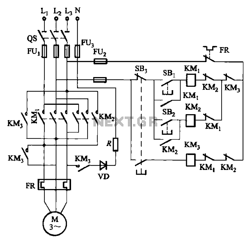
The circuit illustrated in Figure 3-145 employs a rectifier diode brake for neutral grounding in a three-phase, four-wire power supply system. This circuit design incorporates a rectifier diode brake, which plays a crucial role in ensuring the safety and reliability of...
This circuit is designed to connect stereo outputs from four different sources or channels as inputs, allowing only one of them to be selected and connected to the output at any given time. When the power supply is turned...
This is a programmable clock timer circuit that utilizes individual LEDs to display hours and minutes. Twelve LEDs can be arranged in a circular pattern to represent the 12 hours on a clock face, while an additional 12 LEDs...
The circuit's current exceeds the load carried by the rated current meter, prompting the user to immediately cut off the power supply to address the overload. Pressing the reset button restores power, making the system simple, convenient, and practical....
Figure 3-118 illustrates an automatic acceleration control circuit. This circuit employs a male contactor time relay, enabling the motor to start automatically at a low speed before transitioning to high-speed operation. The automatic acceleration control circuit depicted in Figure 3-118...