
Analog electronic clock the whole point of the trigger signal to obtain

An analog electronic clock typically employs a trigger signal to manage its timekeeping functions. The clock's primary components include a quartz crystal oscillator, which provides a stable frequency reference, and a series of counters and dividers that convert this frequency into a usable time format. The trigger signal is essential for synchronizing the movement of the clock hands, usually through a stepping motor or a similar mechanism.
In such a design, the trigger signal is generated at regular intervals, often derived from the output of the frequency divider circuit. This signal activates the stepping motor, which advances the clock hands by a predetermined increment, typically one minute per pulse. The integration of the trigger signal ensures that the clock maintains accurate timekeeping, compensating for any drift in the oscillator frequency.
Additional components may include a power supply circuit to ensure consistent voltage levels, a display mechanism for visual time representation, and a housing to protect the internal circuitry. The overall design emphasizes reliability and precision, making the analog electronic clock a favored choice for both aesthetic and functional applications in timekeeping.Analog electronic clock the whole point of the trigger signal to obtain
Related Circuits

The following method allows the timer to be triggered by a normally closed switch. This would be useful in applications such as intrusion alarms where the protection circuit is broken if a window or door is opened. Trigger Input...

This stereo balance indicator circuit diagram is designed using a few common external components. The schematic circuit is simple to build and provides a visual indication with LEDs for left, right, and center balance. Outputs from each channel are...
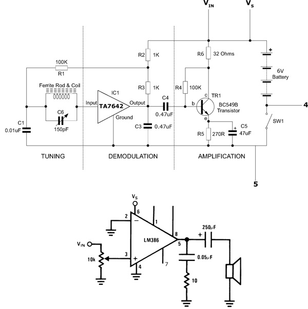
This functioning radio was built for an electronics module. The specified design was modified to include batteries, a switch, and a speaker instead of headphones. An additional amplifier circuit was required to power the speaker driver. Although not necessary,...
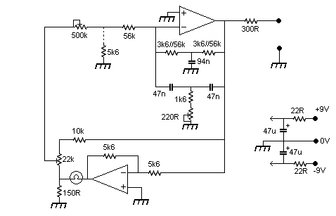
The output level was set to 3.8V peak to peak. The initial objective was to compare several different operational amplifiers (op-amps) before further optimizing the circuit. The op-amps evaluated were the TL072, LM4562, and OPA2134. The distortion spectra are...
Line follower robots are commonly designed to follow a specific path on a track. Typically, these robots are controlled by microcontrollers; however, this article discusses a line follower robot designed without using a microcontroller. The assembly consists of three...
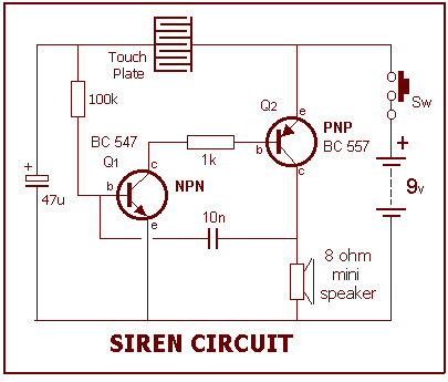
This project is built on the third section of the PC board, identified by "SIREN" and "Project 5." You will notice the similarity between this circuit and the LED FLASHER circuit from project 2. The only differences are the...