
Stereo balance indicator circuit design electronic project

The stereo balance indicator circuit serves as an effective tool for visualizing audio channel balance in stereo systems. It utilizes a differential amplifier configuration with operational amplifier IC1 to compare the amplitude of audio signals from the left and right channels. The outputs of IC1 are then processed by two additional operational amplifiers, IC2 and IC3, which are arranged to detect the relative strength of the audio signals.
In this circuit, the LEDs provide immediate feedback regarding the balance of the audio channels. LED1 indicates a left channel dominance, LED2 signifies a balanced audio output, and LED3 shows a right channel dominance. The choice of common external components facilitates easy assembly and integration into various audio applications.
The operational amplifiers used in this circuit should be selected based on their bandwidth and noise characteristics to ensure accurate signal processing. Power supply considerations are also crucial; the circuit should be powered adequately to prevent distortion of the audio signals.
Overall, this circuit can be implemented in home audio systems, professional sound equipment, or any application where audio channel balance is critical. Proper calibration and testing of the circuit will ensure optimal performance and reliability in signaling audio balance.This stereo balance indicator circuit diagram is designed using few common external components. The schematic circuit is very simple to build and will provide an visual indication with LEDs for left, right and center balance. Outputs from each channel are fed to the two inputs of IC1 connected as a differential amplifier. Output of the IC1 is c onnected to the noninverting inputs of the IC2 and IC3. If the outputs of the IC1 approaches the supply rail, the outputs of the IC2 and IC3 will go high illuminating the LED 3, this will show that the right channel is dominating. If the sound is balanced to the left channel, the Ic2 and IC3 will go low and the LED1 will light. If both channels are equal in amplitude the outputs of the IC2 and IC3 would be low and high respectively, lighting up LED2.
🔗 External reference
Related Circuits
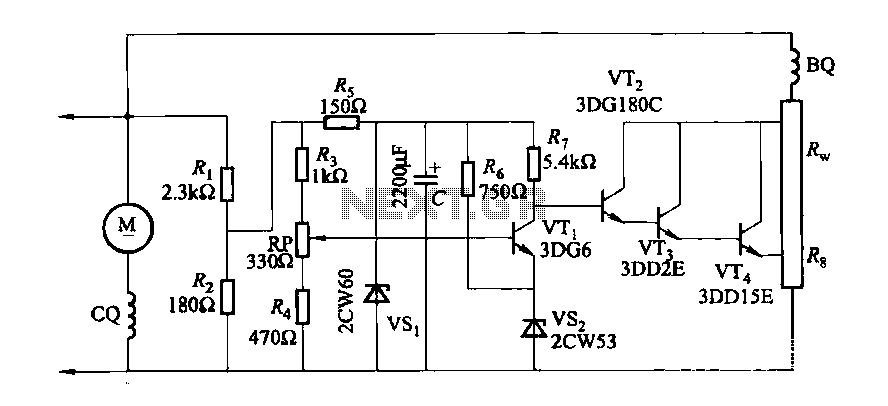
The DC generator automatic voltage regulator circuit is illustrated in Figure 7-53. This circuit is designed for a 40kW, 230V DC shunt complex machine, with a voltage change rate of up to 2.5 percent. In Figure 7-53, BQ represents...
Mechanical contacts have the disadvantage of wearing out. Therefore, it is practical to use an electronic touch switch in certain situations. This type of touch switch utilizes the resistance of human skin for its switching action. The schematic illustrates...
This is a variable power supply controlled by a PIC microcontroller. An LCD display is included in the circuit to show the actual output voltage and current values. A push-button switch is used to adjust the output voltage and...
The two circuits demonstrate the process of opening a relay contact shortly after the ignition or light switch is turned off. The capacitor is charged, and the relay remains closed until the voltage at the diode anode reaches +12...
The simplest method of detecting metal is through a beat frequency oscillator. The circuit consists of two balanced oscillators: one serves as the detector element while the other provides a reference signal. The reference oscillator frequency is set to...
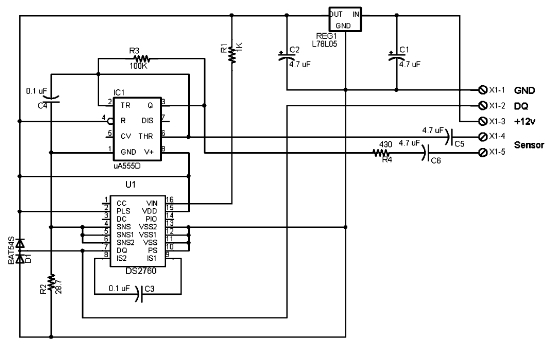
The following circuit illustrates the electrical circuit diagram for the 1976 Dodge Aspen. Features include the current register value of the IC DS2760. The electrical circuit diagram for the 1976 Dodge Aspen is a critical component for understanding the vehicle's...