
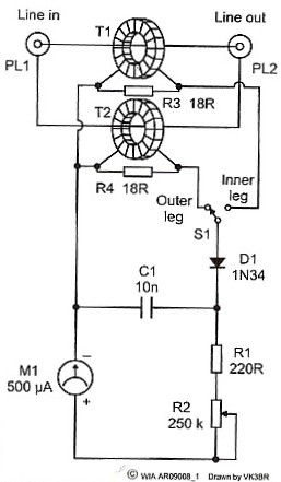
Analog Expanded-Scale Meter For Autos

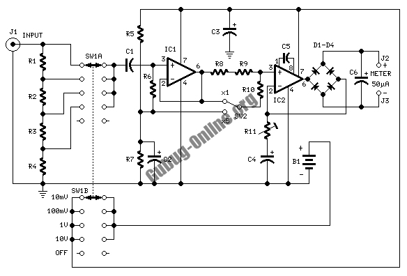
The circuit employs a Zener diode, which is a semiconductor device designed to allow current to flow in the reverse direction when the voltage exceeds a specified value, known as the Zener voltage. In this application, Zener diode D1 is selected to clamp the voltage to a threshold of 6 V. This voltage suppression is crucial for ensuring that the subsequent components in the circuit, such as the analog meter or microcontroller, receive a safe and manageable voltage level for accurate readings.
The configuration of the Zener diode in the circuit typically involves connecting it in reverse bias across the input voltage source. When the input voltage exceeds 6 V, the Zener diode conducts, effectively shunting excess voltage and preventing it from reaching the measuring device. This action not only protects sensitive components from overvoltage conditions but also stabilizes the voltage readings within the desired range.
In automotive applications, monitoring the electrical system is vital for diagnosing issues related to battery performance, alternator output, and overall electrical integrity. The specified meter reading range of 6 to 8 V allows for effective monitoring of various parameters, such as battery voltage under load and charging conditions, ensuring that the automotive system operates within safe limits.
For optimal performance, the Zener diode should be chosen based on its power rating and dynamic resistance characteristics to ensure it can handle the expected current without overheating. Additional components, such as resistors, may be included in the circuit to limit the current through the Zener diode, further enhancing the reliability and accuracy of the monitoring system. Zener diode D1 is used to suppress the first 6 V of the scale, which gives a meter reading of 6 to 8 V—useful for automotive electrical system monitoring.
Related Circuits
If this picture above looks a lot like the Pretty Good LC Meter also on this web site, that's because it's the same meter, but with some significant improvements. At this point, it's a good idea to read the...
This is an electric thermometer circuit composed of the LM134. In the circuit, the voltage or current output by the LM134 is proportional to the thermodynamic temperature, which can be read on a 100 µA meter. The test temperature...
This design circuit is used to activate circuitry and an analog meter for sensitive DC current measurements. A subsequent inquiry raised the possibility of measuring AC microamperes, which inspired the idea for this circuit. The circuit is designed to facilitate...
A digital frostpoint hygrometer was developed for measuring water vapor at NOAA. This new hygrometer was created using AVR microcontrollers and other digital electronics, referencing an old analog instrument. The circuit board layout was designed using Altium DXP, and...
A simple meter is designed to check the balance of currents running in the two legs of a transmission line. This device can evaluate the balance of currents between the inner conductor and the outer coaxial conductor in a...
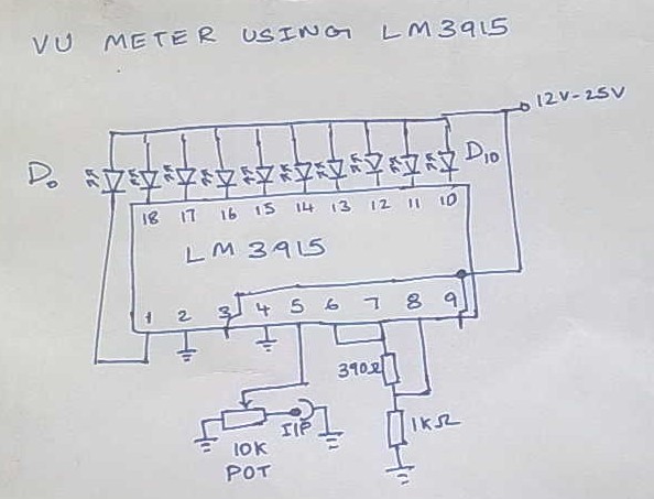
This is Version 1 of the VU meter that has been planned for construction. The final version will differ from the current one as its performance did not meet the requirements. This version cost approximately 100. The IC LM3915...