
The electric thermometer circuit composed of LM134

The electric thermometer circuit utilizing the LM134 is designed to provide accurate temperature readings across a specified range. The LM134 is a precision current source that converts temperature variations into corresponding output currents. This output is directly proportional to the temperature being measured, allowing for a linear response that is easy to interpret.
The circuit typically includes a temperature sensor, such as a thermistor or a thermocouple, which generates a voltage or current signal based on the ambient temperature. This signal is fed into the LM134, which regulates the output current that corresponds to the sensed temperature. The output current is then directed to a 100 µA analog meter, which displays the temperature in a user-friendly manner.
The operational range of this thermometer is from -55°C to 150°C, making it suitable for a variety of applications, including environmental monitoring and industrial processes. The use of a low-voltage power supply is advantageous, as the circuit can function effectively even when the supply voltage drops below 1V, ensuring reliability in low-power scenarios.
For enhanced precision, additional components such as operational amplifiers or calibration resistors may be integrated into the circuit. These components can help fine-tune the output and compensate for any non-linearities inherent in the temperature sensor or the LM134 itself. Overall, this electric thermometer circuit is a robust solution for accurate temperature measurement in diverse settings.This is the electric thermometer circuit composed of LM134. In the circuit, the voltage or current output by LM134 is in proportion to the thermodynamics temperature, which can be read out on the 100?A meter, the test temperature range of the meter is -55?150?. The power supply can work even when the voltage is under 1V, but when the precision requirement i.. 🔗 External reference
Related Circuits
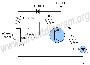
This is a remote tester circuit designed to test TV and other remote controls. The circuit is simple and utilizes only a few components. The infrared sensor used in the circuit is the TSOP1738. When the infrared waves are...

This circuit is a compact timer that keeps the headlights of a car on for approximately 1.5 minutes before turning them off. Incorporating this circuit into a vehicle allows access to dark areas without the need to return and...

A gas leak detector circuit that detects the leakage of LPG gas and alerts the user through audio-visual indications. The circuit operates off a 9V PP3 battery. A Zener diode is used to convert 9V into 5V DC to...

Preamp circuits are used in front of an RF oscillator to create an RF transmitter that is highly sensitive to sound. A microphone preamp must provide stable gain. Preamp circuits play a crucial role in the functioning of RF transmitters...

Gates U1-a and U1-b of the 4093 quad 2-input NAND Schmitt trigger are connected in variable, low-frequency square-wave oscillator circuits. The output of gate U1-a is connected to one of the inputs of gate U1-b. The square-wave output of...

This is a simple FM transmitter circuit schematic diagram that utilizes a single transistor, S9014. The FM transmitter circuit operates by modulating an audio signal onto a carrier frequency, which is typically in the FM band. The S9014 transistor serves...