
analog to digital converter module

The ADC 0809 is a widely used analog-to-digital converter that facilitates the conversion of analog signals into digital form, suitable for processing by a microcontroller. The architecture of the ADC 0809 consists of a series of functional blocks, including an analog input stage, a sample-and-hold circuit, a successive approximation register (SAR), and a digital output stage.
The pin configuration of the ADC 0809 is critical for its operation. The 8 analog input pins (labeled A0 to A7) allow for the connection of various analog signal sources. The digital output pins provide the converted binary data. The control pins, including the start of conversion (SOC) and end of conversion (EOC), are essential for synchronizing the conversion process with the microcontroller.
In practical applications, the ADC 0809 is typically interfaced with a microcontroller through its data and control lines. The microcontroller sends a signal to initiate the conversion process via the SOC pin. Once the conversion is complete, the EOC pin goes high, indicating that the digital output is ready for retrieval. The microcontroller can then read the converted data from port 0, which corresponds to the binary representation of the analog input signal.
The use of filter capacitors, such as the 10µF and 100µF capacitors mentioned, is crucial in ensuring the integrity of the analog signal prior to conversion. These capacitors smooth out voltage fluctuations and suppress high-frequency noise, which can adversely affect the accuracy of the conversion process. The LED indicator provides a visual confirmation of the circuit's operational status, allowing for quick diagnostics and troubleshooting.
Overall, the ADC 0809 is an essential component in systems requiring precise analog-to-digital conversion, enabling microcontrollers to process real-world signals effectively.Analog to Digital converter modules are used in Micro controller based projects where the analog signals are required to be converted into digital signal for further processing in Micro controller. The integrated chip used for this purpose is 0809 ADC. This post describe briefly the PIN diagram, block diagram and details of this specified chip her e. The ADC totally consists of 28 pins with 8 inputs and 8 outputs. The output from the filter is given to pin 26 of ADC 0809 shown in the figure above. The address channels A, B, C are grounded so that channel 1 is enabled. The digitized output from the converter is given to port 0 of micro controller. The control signals from the ADC are given to port 2 of the Microcontroller. This circuit follows the principle of successive approximation method and when the start of conversion goes high, it marks the beginning of the process and high end of conversion marks the end of it. The two capaciors 10F and 100F acts as filter. The filter capacitors in the circuit remove the low and high frequency noises. The LED is used to check the proper functioning of the circuit. 🔗 External reference
Related Circuits
The power is measured by the circuit AD8307 over a 50 ohm dummy load. An A/D converter of 12 bit converts the analog output from the AD8307 to a digital number. Since the AD is a 12 bit A/D,...
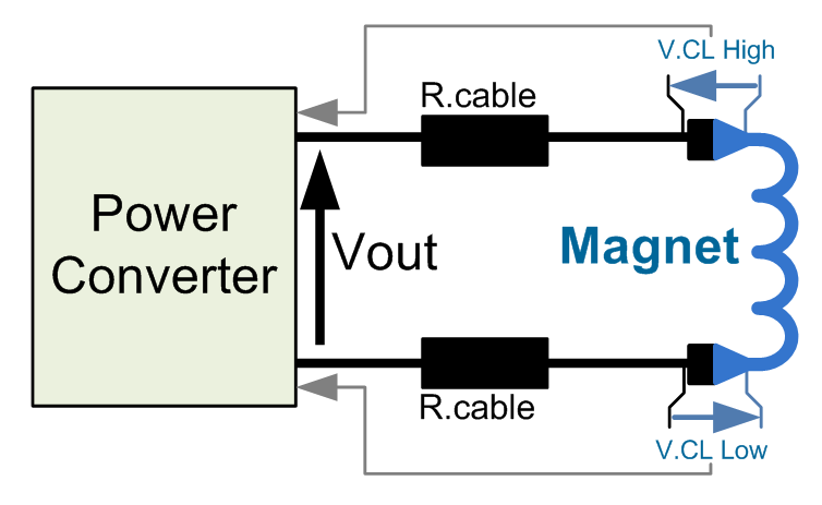
This power converter is utilized in the LHC machine to supply power to superconductive magnets. It is situated in the underground installation of the LHC, in proximity to the loads to minimize cable losses. The voltage source employs a...
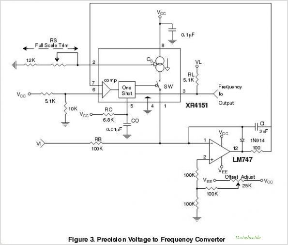
The purpose of this application note is to present an example circuit illustrating the operation of the XR-T5683 device at a data rate of 10.1 Mbps. This note includes the results of measurements taken on the XR-T5683 at this...
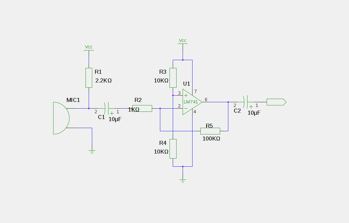
An electret microphone has been connected to an operational amplifier (op-amp), with the output directed to an Arduino microcontroller. The analog-to-digital converter (ADC) on the microcontroller converts a voltage range of 0 to 5 volts into a 10-bit number,...
A highly accurate digital thermometer utilizing an LM35 probe with a resolution of 0.1 degrees Celsius. The circuit includes two adjustable components. The first, R5, is used to calibrate the display to zero. To perform this calibration, the end...
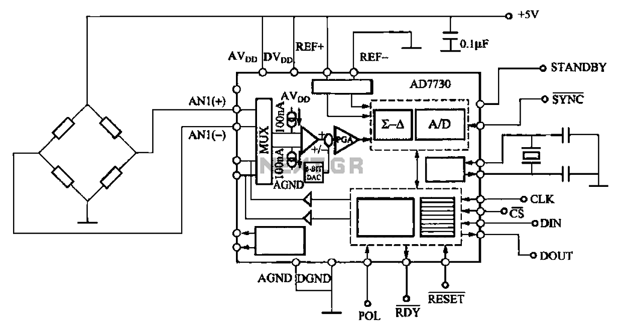
AD7710/7715/7730 multifunction digital sensor signal conditioning integrated circuits (ICs) that combine a digital interface with a control port, a clock generator, a digital filter, amplitude modulation, a programmable gain amplifier, an analog-to-digital (A/D) converter, and additional electrical pathways. The...