
Linear light-meter circuit
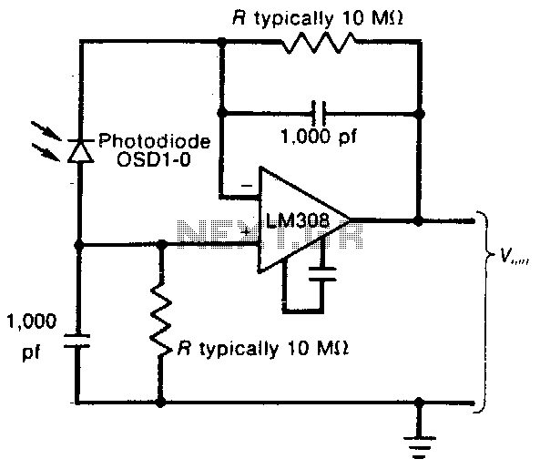
The described circuit utilizes a low-input-bias operational amplifier, which is advantageous for applications requiring minimal offset voltage and drift, ensuring accurate light level readings. The op amp is configured in a non-inverting configuration to amplify the input signal derived from a light-dependent resistor (LDR) or photodiode, which changes resistance based on the ambient light conditions.
The resistor Rl plays a crucial role in setting the gain of the circuit. By adjusting Rl, the sensitivity of the circuit can be tailored to specific light levels. However, it is important to maintain Rl at a minimum value of 100 kΩ to prevent excessive noise and instability in the output signal, which could compromise the accuracy of the light level indication.
Capacitors in the circuit are carefully selected to create a time constant that smooths out rapid fluctuations in the light signal. This filtering is essential in environments where light levels may vary quickly, such as under fluorescent lighting, which can produce flicker at higher frequencies. The time constant, determined by the product of the resistance and capacitance values, should be optimized to balance responsiveness to genuine changes in light levels while effectively rejecting high-frequency noise.
Overall, this circuit design effectively combines the precision of a low-input-bias op amp with carefully chosen resistive and capacitive components to deliver a reliable and stable DC output that reflects ambient light conditions, making it suitable for various applications in light sensing and control systems.This circuit uses a low-input-bias op amp to give a steady dc indication of light level. To reduce circuit sensitivity to light, Rl can be reduced, but should not be less than 100 K The capacitor values in the circuit are chosen to provide a time constant sufficient to filter high-frequency light variations that might arise, for example, from fluorescent lights. 🔗 External reference
Related Circuits
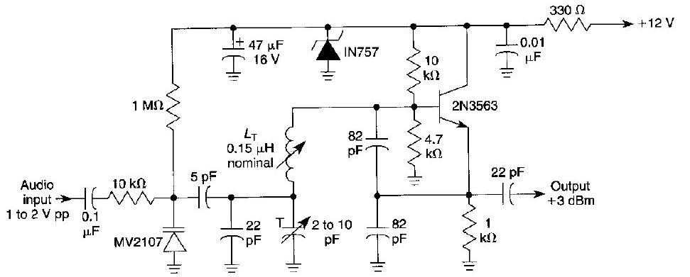
This FM oscillator can be utilized for wireless audio, microphone, and part-15 applications where a stable frequency-modulated oscillator is required. The FM oscillator is an essential component in various communication systems, particularly in wireless audio transmission and microphone applications. It...
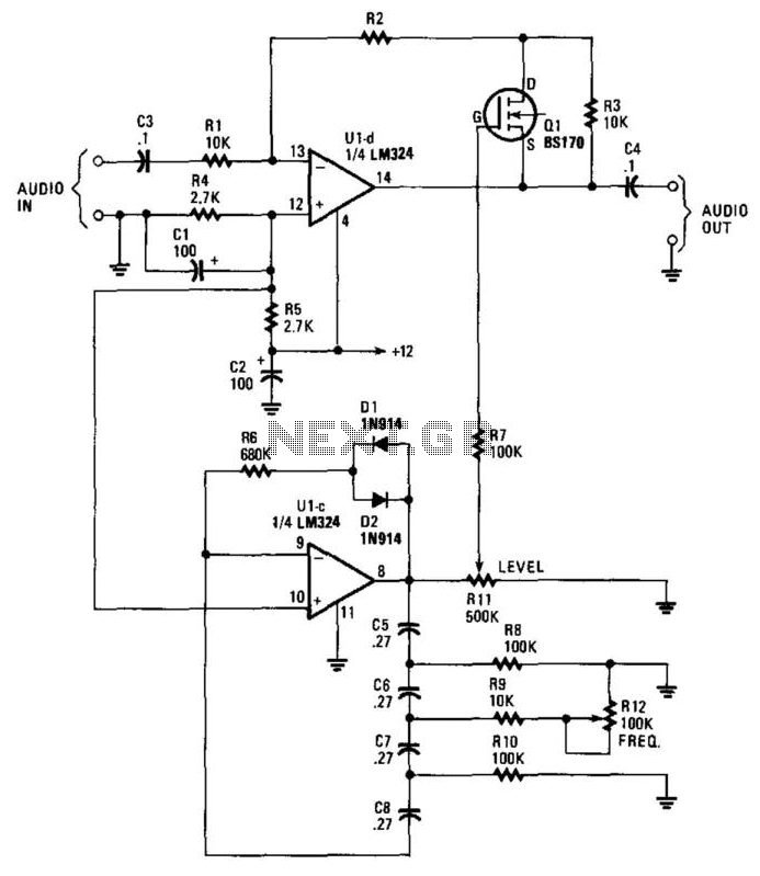
This circuit incorporates a Very Low Frequency (VLF) Amplitude Modulation (AM) component into an audio signal. This effect is commonly utilized in musical instruments. U1C, a phase-shift oscillator functioning at a few Hertz, generates a signal that modulates the...
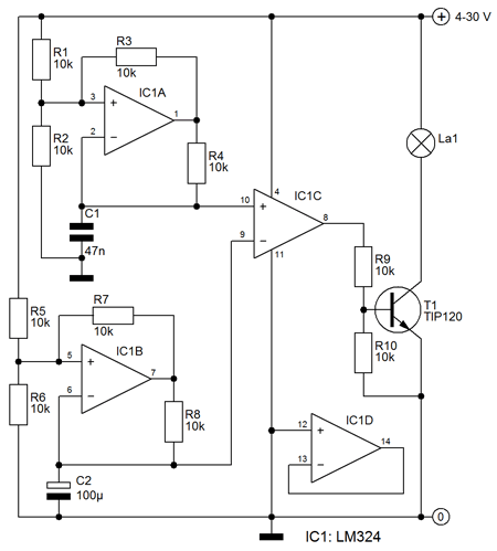
This circuit ensures that a blinking slowly, ie the lamp is brighter lights until a maximum is reached and then gradually decrease in strength until the lamp is off. IC1a opamp is used here to a triangular voltage generation....
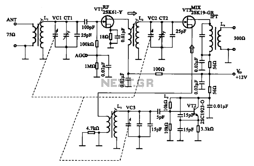
The FM radio circuit consists of a high-frequency amplifier (VT1), a mixer and local oscillator (VT2), and additional components. The circuit includes an FM radio antenna for signal detection, with an input transformer (L1) connected to a gate transistor...

This circuit is a compact timer designed to keep the headlights of a car illuminated for approximately 1.5 minutes before automatically turning them off. By integrating this circuit into a vehicle, users can access dark areas without the need...
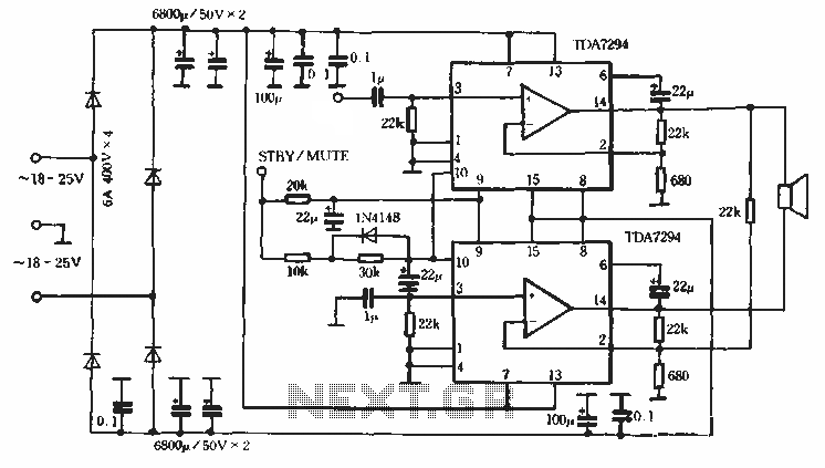
Europe's leading SGS-THOMSON STMicroelectronics recently introduced a new power integrated amplifier, the TDA7294, to the Chinese mainland market. This amplifier, characterized by a cold and hard tone, is particularly suited for Hi-Fi applications such as home theaters and active...