
One Transistor FM Radio With Improved Audio Gain

The one-transistor FM radio circuit utilizes a super-regenerative architecture, which is known for its simplicity and efficiency in receiving FM signals. The core component of the circuit is a single transistor, which serves both as the radio frequency (RF) amplifier and the detector. This design significantly reduces the number of components required, making it compact and cost-effective.
In this schematic, the transistor is configured to operate in the super-regenerative mode, which allows for improved sensitivity and audio gain compared to traditional radio designs. The circuit typically includes an LC tank circuit, consisting of an inductor and a capacitor, which is tuned to the desired FM frequency. This tank circuit is crucial as it selects the frequency of the incoming signal while simultaneously providing feedback to the transistor to enhance its gain.
Additional components in the circuit may include resistors for biasing the transistor, capacitors for coupling and bypassing, and possibly a variable capacitor to allow for fine-tuning of the frequency. An audio output stage is also included, which may consist of additional transistors or operational amplifiers to further amplify the audio signal before it is sent to a speaker or headphones.
The design benefits from a minimalistic approach, making it suitable for educational purposes, hobbyist projects, or low-cost radio applications. The improved audio gain achieved through the super-regenerative design enhances the listening experience by providing clearer and more robust sound output.The following circuit shows a Schematic diagram for the One Transistor FM Radio with Improved Audio Gain. Features: super-regenerative design, .. 🔗 External reference
Related Circuits
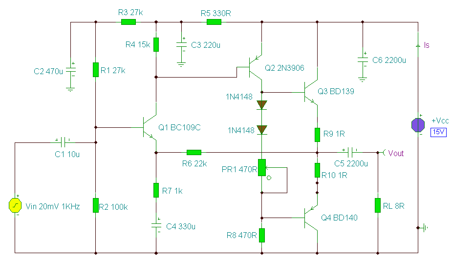
The circuit presented is a straightforward yet efficient amplifier that can provide notable performance enhancements. This amplifier can demonstrate negative resistance at lower settings of the 500-ohm potentiometer, resulting in increased gain or even oscillation. Consequently, the circuit can...

This circuit can be directly connected to CD players, tuners, and tape recorders. It requires the addition of a 10K logarithmic potentiometer (dual gang for stereo) and a switch to accommodate various sources. Proper grounding is crucial to eliminate...

Electronic FM Telephone Transmitter Schematic. The following schematic design illustrates a circuit diagram for an FM telephone transmitter built on a compact PC board layout. This small design allows it to be easily integrated within the housing of a...
A 2 Watt audio amplifier made from discrete components. This was one of the earliest circuits that I ever designed and built, in Spring 1982. At that time I had only an analogue meter and a calculator to work...

A small headphone amplifier is a valuable device capable of driving multiple pairs of headphones. The headphone amplifier's task is simplified due to the relatively low output power requirements and the manageable load characteristics. Headphones generally have an impedance...

1-Transistor FM Transmitter. R1 27k, R2 56k, R3 12k, R4 100, C1 1u, C2, C3 470p, C4 6 to 10p, C5 1-30p trimmer, L1 etched on PCB. The 1-transistor FM transmitter is a compact electronic circuit designed to transmit audio...