
Animation with Servos

The servo motor operates based on a feedback system that ensures precise control of the output shaft. The internal components typically include a DC motor, a potentiometer for position feedback, and a control circuit. The control circuit interprets the incoming pulse width modulation (PWM) signals and adjusts the motor's position accordingly. The gear mechanism amplifies the motor's torque, allowing the servo to handle loads effectively.
In applications such as robotics, model airplanes, and animatronics, the ability to control the servo with high precision is crucial. The typical 180-degree rotation allows for a wide range of motion, making servos suitable for applications requiring accurate positioning. The use of a microcontroller, such as the PICAXE, simplifies the process of generating the necessary control signals. The microcontroller can be programmed to produce varying pulse widths based on user input or sensor feedback, enabling dynamic control of the servo's position.
For example, in a model railroad application, the PICAXE can be programmed to respond to track sensors, adjusting the position of the servo to switch tracks or activate signals based on train location. This adaptability makes it an ideal choice for hobbyists and engineers looking to implement automated solutions in their projects. The integration of servos into electronic designs enhances functionality and provides a foundation for creating complex systems with precise control capabilities.A servo contains a small motor and gear box that rotates a shaft to a precise location and holds it there. This photo shows a typical servo with its top removed. The position of the shaft is based on a digital signal. Most servos rotate through a 180 degree arc while delivering a good bit of torque. Three wires connect the servo to its controller. Two of the wires connect to a source of DC power, normally 5 to 6 volts. The other wire to the servo receives pulses from the controller that tell the servo where to position its shaft. In the photo below the red wire goes to the positive terminal of the power supply, the black wire goes to the negative and the white receives the positioning pulses.
The control pulses are spaced 20 milliseconds apart and the length of each pulse determines where the servo`s shaft will come to rest. A 1. 5 millisecond pulse will place the shaft in its center position, sometimes referred to as "neutral". A shorter pulse of 1. 25 ms will rotate the shaft 90 degrees to the right while a longer pulse of 1. 75 ms will rotate the shaft 90 degrees to the left. In a model airplane radio control system these pulses are generated by the airplane`s radio receiver.
The length of the pulses is determined by the position of the radio control transmitter`s joystick. This video shows a servo with a digital oscilloscope screen in the background. The square wave on the oscilloscope`s screen gives a visual representation of the control pulses. Note that the square wave gets smaller as the servo rotates in a clockwise direction and elongates as the servo rotates counter clockwise. We could use radio control transmitters and receivers to control the servos that we use for animation in our layouts but there is a much simpler, more versatile and less expensive alternative.
All we need is a device that can deliver an appropriate string of pulses to the servo. This can be done with any number of electronic circuits but the easiest to construct and utilize may be one utilizing the PICAXE microcontroller. I have written a number of articles that describe model railroad applications based on the PICAXE including a Robot Train, Morse Code Beacon, Flashing Ditch Lights and a Lighthouse Controller.
I encourage you to read these articles for more information on the capabilities o 🔗 External reference
Related Circuits
Circuit to control RC servos using 0-10V control voltage This circuit is designed to control RC servos by utilizing a control voltage range of 0 to 10 volts. The operation of the circuit is based on the principle of converting...
The monostable 555 timer multivibrator circuit, also known as a one-shot monostable multivibrator, functions as a retriggerable pulse generator. The term "monostable" indicates that the circuit has only one stable state, with the unstable state referred to as the...

The circuit is designed to fit snugly, eliminating the need for adhesive. It is recommended to test the fit multiple times, making incremental adjustments until a snug but movable fit is achieved. The entire circuit should be placed inside...
A servo is a general term for an automatic control system, derived from the Latin word "servus," meaning slave. It refers to a mechanism that can be set and forgotten, self-adjusting during operation through feedback. For instance, disk drives...
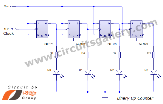
This document discusses an Asynchronous 4-Bit Binary Up Counter, a circuit constructed from several J-K flip-flops connected in a cascade configuration to produce a four-bit counting sequence. An up counter is a digital counting circuit that increments its count...
%2Bwith%2Banimation%2Bsimulation%2Bcircuit.png)
The Johnson digital counter, also known as the Twisted Ring Counter, is a synchronous shift register that incorporates feedback from the inverted output (Q`) of the last flip-flop. The Q` output of the final flip-flop is connected back to...