
Johnson digital counter circuit diagram using D flip flop 7474 (3 bit/4 bit) with animation/ simulation
%2Bwith%2Banimation%2Bsimulation%2Bcircuit.png "Johnson digital counter using D flip flop 7474 (3 bit/4 bit) with animation/ simulation")
The Johnson counter is characterized by its unique counting mechanism, which is facilitated by the feedback loop that introduces a delayed inversion of the last flip-flop's output. This allows the counter to produce twice the number of states compared to a traditional ring counter. The circuit typically consists of a series of D flip-flops configured in a chain, where the output of one flip-flop serves as the input for the next.
In practical implementations, the 7474 D flip-flop is commonly used due to its reliability and availability. Each flip-flop in the Johnson counter is clocked simultaneously, ensuring synchronous operation. The initial state of the counter can be set by applying a logic high to the first flip-flop, which will propagate through the chain upon receiving clock pulses. The counter's output can be monitored at various stages, allowing for the observation of the counting sequence as it progresses through its states.
To extend the Johnson counter beyond three bits, additional D flip-flops can be added in series, with the final flip-flop's Q` output still being fed back to the first flip-flop's D input. This modularity makes the Johnson counter a versatile choice for various digital applications, including LED control, frequency division, and other tasks requiring a reliable sequence of states. The simplicity of the circuit, combined with its efficient use of flip-flops, makes it an attractive option for digital design.The Johnson digital counter or Twisted Ring Counteris a synchronous shift register with feedback from the inverted output (Q`) of the last flip-flop. Q` of the last flip flop is connected back to the input D of the first flip-flop. This inversion of Q before it is fed back to input D causes the counter to count in a special way. Animation/ simu lation of this Johnson counter circuit is also given in this article. You can create simple dancing LED effects using this synchronous Johnson digital counter. The main benefit of this type of counter is that it only needs half the number of flip flops compared to that of standard ring counter to represent many states. So an n-stage Johnson counter givies a sequence of 2n different states and can therefore be treated as a Mod 2n counter whereas an n-stage ring counter has only n states that is Mod n counter .
Above circuit diagram represents a 3 bit Johnson counter using 7474 D flip flop. You can easily extent this circuit upto 4 bit, 5 bit, etc. by adding flip flops after the 3rd flips flop. This logic 1 is appears at the input of 1st flip flop. During the first clock pulse this logic 1 is transferred to the output of 1st flip flop. Thus the total output of Johnson counter is 100. Then input of 1st and 2nd flip flop is logic 1 and after the second clock pulse these inputs appear at the outputs of 1st and 2nd flip flop. So the total output is 110. During this state (111) the time inverted output (Q`) is logic 0. This 0 is fed to the 1st flip flop. Then the 0 will circulate through the flip flops as 011, 001, 000. 🔗 External reference
Related Circuits
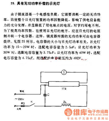
The fluorescent lamp with reactive power compensation operates with a ballast that acts as an inductive load. This inductive load requires reactive power, which leads to a decrease in the power factor of the fluorescent lamp. A lower power...
This sawtooth generator circuit utilizes a 741 operational amplifier (op-amp) and functions as a musical sound synthesizer. The sawtooth input signal is continuously modified through potentiometer P2 to create varying waveforms. The sawtooth generator circuit primarily employs the 741 op-amp...
Due to the varying conditions of different input signals, when an abnormal voltage is applied to the pin, protection circuits are established to create a circuit path from the LSI (large scale integration) circuits for internal protection. The structure...
The circuit operation begins by transmitting stereo surround sound signal quality information through the master volume circuit. This drives the left channel connected to the LCH Model TL072 IC1A and IC1B, which are linked to the right channel (Rch)....
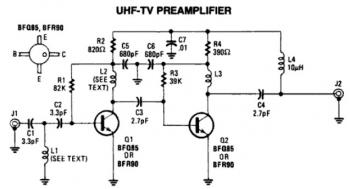
This is a low-cost, antenna-mounted UHF TV pre-amplifier circuit that can provide more than 25 dB of gain. The first stage of the pre-amplifier is biased for optimum gain. L1 and L2 are strip line equivalents with a length...
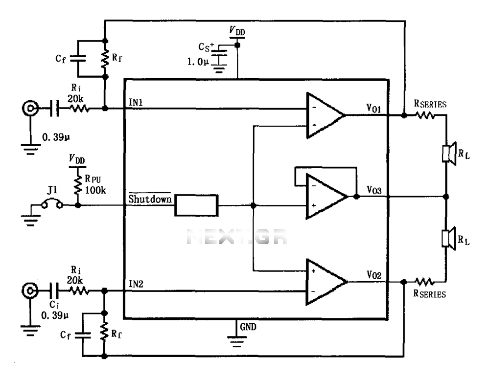
The circuit for the LM4910 is designed to minimize output noise and reduce power consumption. The output noise is attenuated by utilizing a resistor in series with the load. A feedback resistor Rf is used in conjunction with a...