
Binary Up Counter Circuit with working animation and simulation video

The Asynchronous 4-Bit Binary Up Counter operates by utilizing four J-K flip-flops, where each flip-flop represents one bit of the counter. The J-K flip-flop is a versatile digital memory circuit that can toggle its output based on the input conditions. In this configuration, the flip-flops are connected in such a way that the output of one flip-flop serves as the clock input for the next flip-flop in the sequence, creating an asynchronous behavior.
When the counter is activated, the least significant bit (LSB) flip-flop toggles its state with each clock pulse. This toggling occurs at a frequency determined by the clock signal fed into the first flip-flop. Each subsequent flip-flop toggles its state on the falling edge of the previous flip-flop's output, effectively dividing the frequency by two for each additional flip-flop. As a result, the counter counts in binary from 0000 to 1111 (0 to 15 in decimal).
In designing the circuit, careful attention must be given to the setup and hold times of the J-K flip-flops to ensure reliable operation. The circuit can be powered by a standard DC supply, and it is important to include debounce circuitry if mechanical switches are used to initiate the clock pulses.
Simulation tools can be employed to visualize the counting sequence and verify the operation of the counter. The accompanying video provides a practical demonstration of the circuit assembly, illustrating how to connect the components and observe the output states as the counter progresses through its counting sequence.
Overall, the Asynchronous 4-Bit Binary Up Counter is a fundamental digital circuit that serves as a building block for more complex counting applications in digital electronics. Its ease of implementation and straightforward design make it an excellent choice for educational purposes and practical applications alike.Here we are going to discuss about an Asynchronous 4 Bit Binary Up Counter, a circuit made up of several J-K flip-flops cascaded to generate four bits counting sequence. An up counter is basically a digital counting circuit which counts up in an incremental mode. Here we have given the simple counting circuit setup using 4 flip flops and a simulat ion video for better understanding. For simplicity, an animation outputofelectronic counter sequence is also provided with this article. After reading this article you will be able design Up Counter circuits easily. Watch this video of Binary Up Counter circuit simulation. In this video we have showed the step by step circuit assembly and output working of Digital 4 bit up counter circuit. You can also visit out Video Gallery for other videos. 🔗 External reference
Related Circuits
The schematic presented is a project for a simple temperature sensor circuit, also referred to as a heat sensor circuit, which activates an LED in response to heat. The circuit is straightforward to construct and requires only a few...
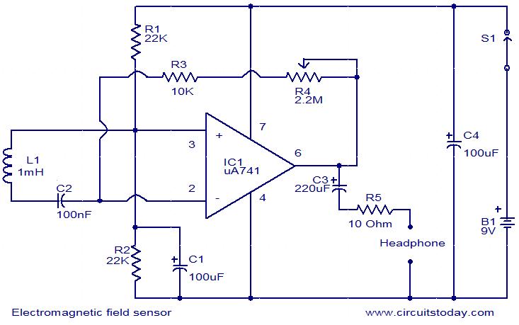
The following circuit illustrates an Electromagnetic Field Sensor Circuit Diagram. This circuit is based on the uA741 integrated circuit. Features: it is used to sense electromagnetic fields. The Electromagnetic Field Sensor Circuit utilizes the uA741 operational amplifier to detect variations...
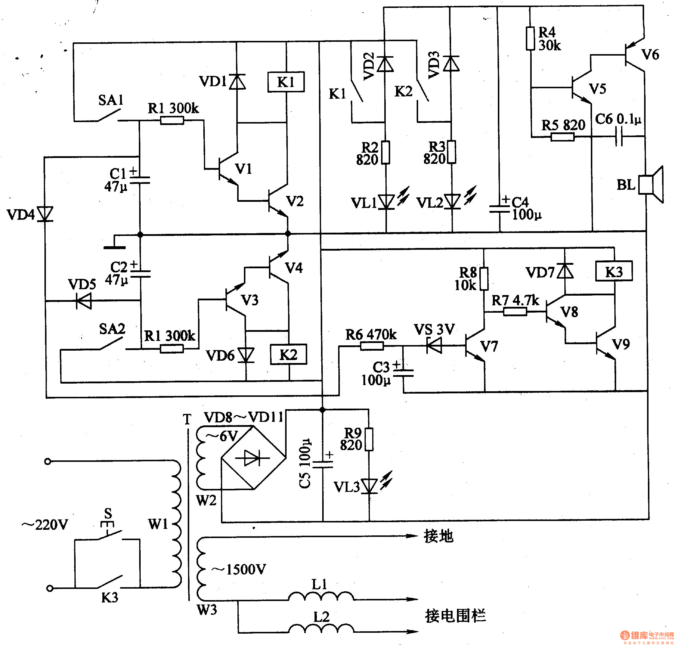
The electric fence control circuit includes a +6 V power supply circuit, a high-voltage output circuit, a trigger control circuit, an alarm circuit, and a protection circuit. The +6 V power supply circuit consists of a power control button...
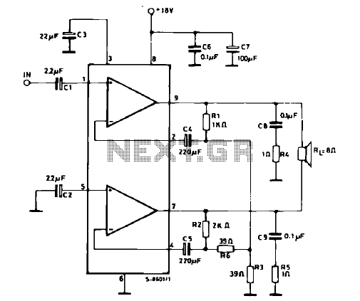
The schematic illustrates a 12 W Bridge Amplifier circuit diagram utilizing the TDA2007A, a class AB dual audio power amplifier. This amplifier is specifically designed for stereo applications in music centers, television receivers, and portable radios. As stated in...
A thermistor is utilized in the circuit for heat sensing, while two 5K variable resistors are incorporated to calibrate the circuit for activating the relay at the desired temperature. The inclusion of a 1N4007 diode across the relay serves...
555 low power timing circuit diagram. The diagram is from the technical information of Chinaicmart. For more detailed information about the circuit diagram. The 555 timer IC is widely utilized in various applications due to its versatility and ease of...