
Another simple DC protection

The circuit is designed to monitor the audio output for any DC offset, which can damage speakers. The L-In and R-In inputs receive audio signals directly from the speaker terminals, ensuring that the monitoring occurs at the point of audio output. The power supply provides dual polarity voltages of +25V and -25V, which are essential for the proper operation of the circuit's components, particularly the transistors and relays.
Transistor Q2 plays a critical role in the detection of DC signals. When the circuit senses a DC voltage, Q2 is activated, leading to a significant voltage drop across resistors R4 and R5. This voltage drop is designed to produce a regulated 5V output, which is necessary for powering the PIC multiprocessor. The PIC serves as the central control unit, capable of executing programmed instructions to manage the operation of the relays and LED indicators.
The inclusion of two 12V relays with their coils wired in series allows for a reliable disconnection of the speaker output when DC is detected. The relays are powered from dedicated terminals, Rel+ and Rel-, ensuring that they operate effectively. The choice of relays provides a robust solution for breaking the audio path, preventing potential damage to the speakers.
Furthermore, the programmability of the PIC enables the incorporation of customizable features, such as adjustable delay times before the relays engage or disengage. This flexibility allows for tailored operation based on specific requirements. Additionally, the PIC can control an LED indicator, providing a visual alert when DC detection occurs, enhancing user awareness of the circuit's operational status.
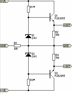
Overall, this circuit effectively combines audio monitoring with protective measures, utilizing modern microcontroller technology to ensure reliable performance and user configurability.I used some schematics from Elliot sound products to help with this circuit. L-In and R-In come straight from the speaker terminals, +ve and -ve are +25 and -25 volts from the power supply. When the circuit detects DC, transistor 2 is turned on and the 25 volts is dropped across R4 and R5 to give 5 volts.
This can then be used by the PIC multiprocessor.
There will be 2 x 12 volt relays with there coils in series fed from Rel+ and Rel-. These will be used to break the speaker output. Obviously, because a PIC is used here, any delay can be programmed into it and it can also flash the LED when the detection is sensed.
🔗 External referenceRelated Circuits
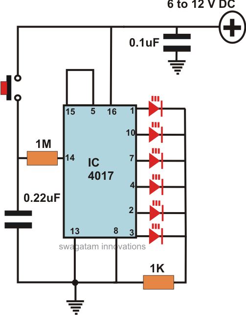
This article offers a circuit diagram and a discussion on CMOS logic and IC layout for creating a set of attention-getting LED running lights. It details a simple sequential LED flasher or light chaser that can be built, including...
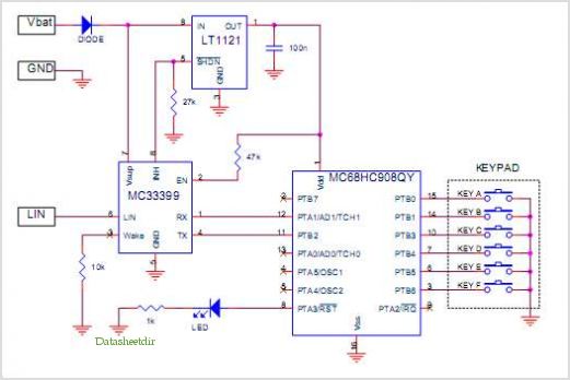
Introduction The design of off-line constant voltage, constant current (CVCC) power supplies using the NCP1014 for devices such as cell phones, hand tools, and similar battery chargers can present various challenges when low cost and circuit simplicity are required...
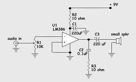
The schematic diagram presented is of a twin "T" phase shift oscillator, an audio oscillator. This oscillator derives its name from the phase shift network formed by resistors R3, R4, and capacitors C1, C2, and C3. This network shifts...
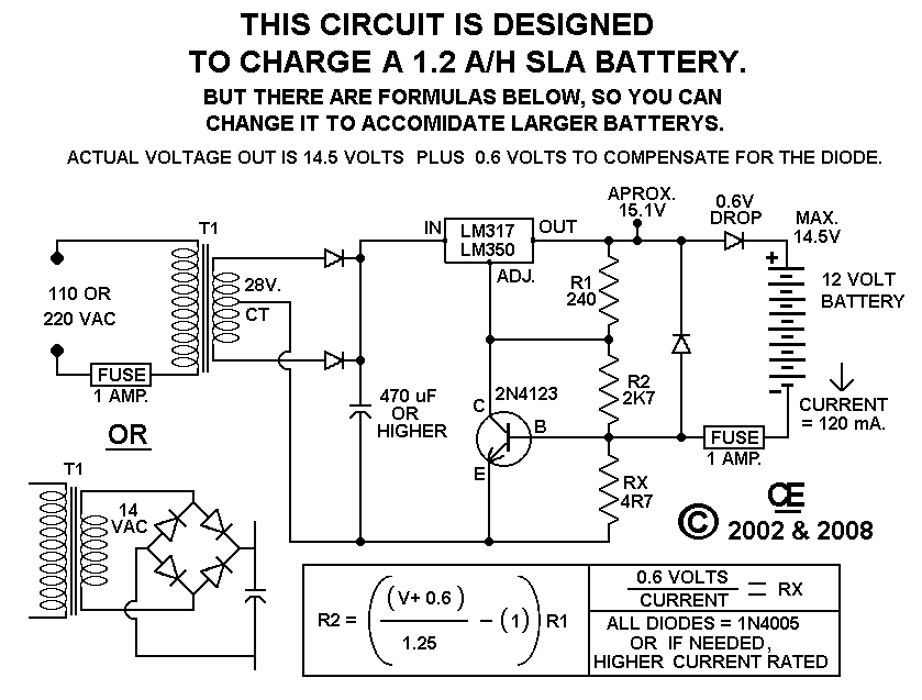
This circuit provides effective charging results for Gel Cell or Sealed Lead Acid (SLA) type batteries, which are utilized in metal detector projects. It can be modified to accommodate higher current batteries and is likely suitable for batteries with...

The schematic for this project flows naturally from left to right, starting with the antenna and the regenerative receiver front-end, followed by amplification stages, and concluding with the 555 timer. This regenerative receiver front-end is commonly found in circuits...
There will be many occasions when it is beneficial to utilize the P05 supply module sourced from a higher voltage supply. For instance, this could be advantageous when integrating balanced inputs. The P05 supply module is designed to facilitate the...