
how to build a simple led light chaser circuit

The schematic for the LED running lights features the CMOS 4017 decade counter, which is designed to sequentially activate a series of LEDs in a chaser pattern. The 4017 IC operates by counting clock pulses generated by the 4049 oscillator, which serves as a square wave generator. This oscillator can be configured to produce a desired frequency, thus controlling the speed of the LED sequence.
In the circuit, the output pins of the 4017 are connected to individual LEDs, which are typically arranged in a linear or circular pattern for visual effect. Each output pin corresponds to a specific LED, turning it on in succession as the counter increments. The circuit can be enhanced with resistors to limit current through the LEDs, ensuring they operate within safe limits.
The design may also include a capacitor connected to the oscillator to stabilize the frequency and improve performance. A power supply, typically 9V or 12V, is required to power the circuit, and appropriate bypass capacitors should be placed near the ICs to filter out noise and stabilize operation.
The schematic should also include a brief explanation of how to set up the components on a breadboard or PCB, along with any necessary connections for the power supply and ground. With careful assembly, this circuit can effectively create an eye-catching display of running lights suitable for various applications, such as automotive lighting or decorative displays.Want to make a set of attention-getting LED running lights? This article provides a circuit diagram and discussion of the CMOS logic and IC layout for a simple sequential LED flasher or light chaser that one can build, including the parts lists. The heart of the project is the CMOS 4017 Logic IC paired to an IC 4049 oscillator.. 🔗 External reference
Related Circuits
A simple function generator that produces a specific frequency. While awaiting the arrival of the AD9832 chip, a basic version of a Direct Digital Synthesis (DDS) synthesizer was developed using only the AT2313 microcontroller and a resistor network. This...
This RS232 power supply circuit diagram is a simple RS-232 line driver power supply that operates from an input voltage as low as 4.2V and delivers an output of ±12V at ±40 mA with an efficiency of better than...
To complement the 60 Watt MOSFET audio amplifier, a high-quality preamplifier design was necessary. A discrete components topology using +24V and -24V supply rails was chosen, minimizing the transistor count while still achieving low noise, very low distortion, and...
The DC panel battery is commonly utilized in power plants and substations within DC systems. To enhance the safety and reliability of the current system, an uninterrupted power supply switching circuit may be implemented. This circuit includes components such...
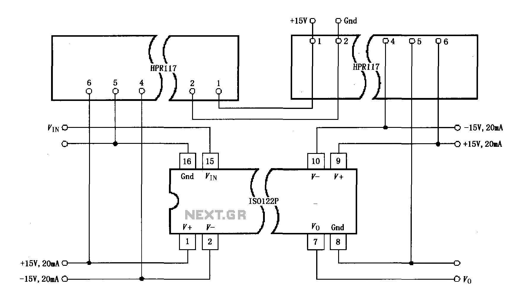
Power isolation is demonstrated for the ISO122P / 124, which features a three-port amplifier. The circuit also utilizes precision analog isolation amplifiers. The ISO122P / 124 isolation amplifier is a cost-effective solution, and the HPR117 DC/DC converter component provides...
This circuit was designed on request and can be useful to those wishing to have, say, a red LED illuminated when an appliance is on and a green LED illuminated when the same appliance is off. Any mains operated...