
Another simple H-Bridge circuit

The described circuit employs an H-bridge configuration utilizing four transistors, functioning as electronic switches to control an electric motor's direction and operation. The transistors are arranged in such a way that they can either allow current to flow in one direction or the opposite, thus enabling bidirectional motor control.
In this configuration, two signal lines are used to control the transistors. The operation modes are defined as follows:
1. **Both Transistors Off**: When both signal lines are inactive (both transistors are off), the motor remains stationary. In this state, the circuit may exhibit a shorted condition if not properly designed, which could potentially damage the motor or other components.
2. **S1 On, S2 Off**: Activating the first signal line while keeping the second off allows current to flow through one pair of transistors, reversing the polarity across the motor terminals. This causes the motor to rotate in the reverse direction, from the negative terminal (indicated as blue) to the positive terminal (indicated as red).
3. **S1 Off, S2 On**: Conversely, activating the second signal line while deactivating the first allows current to flow through the alternate pair of transistors. This configuration causes the motor to rotate in the normal direction.
It is critical to note that when using standard transistors, additional protective diodes should be connected in parallel with each transistor. This precaution is necessary to prevent damage from back EMF (electromotive force) generated by the motor when it is switched off. The diodes will provide a safe path for the current generated by the motor, protecting the transistors from overvoltage conditions that could lead to failure.
When designing the circuit, it is advisable to select transistors that can handle the expected load current of the motor. The use of power transistors is recommended for applications involving larger motors to ensure reliability and prevent component burnout. Proper heat dissipation measures should also be considered, as excessive current can lead to overheating and potential damage to the transistors.
Overall, this H-bridge circuit is a straightforward and effective solution for controlling small DC motors in various applications, provided that the necessary precautions are taken to safeguard the components involved.You have 4 transistors, wired as ON OFF switches. Two signal lines allow you to run the motor in one direction, when reversed, the motor runs in the other direction. It's very straightforward to use and build, but be careful to use only small motors, as the currents drawn from the bigger types can burn your components.
An H bridge is a kind of circuit you use to control the direction (and sometimes speed) of an electric motor, using only a single polarity voltage (you need to reverse the way current flows in order to reverse the way the motor rolls). There are 3 modes of operation: Both equal ( on or off ): motor doesn't run, as it's shorted or not connected S1 on, S2 off: motor runs in reverse ( from negative [blue] to positive [red] ) S1 off, S2 on: motor runs normal. Also note, unless you use power transistors, you need to connect diodes across the transistors in order to protect from overvoltages.
🔗 External reference
Related Circuits
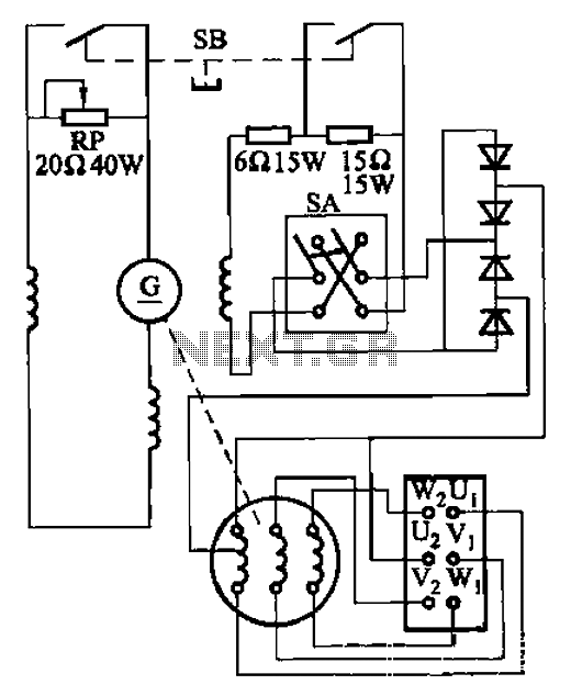
The AX3-300-2 DC arc welding machine circuit is part of the AX, AX1, AX3, and AR series of rotary DC arc welding machines. These machines share a similar structural design, featuring a three-integral unit configuration that combines an inverter...
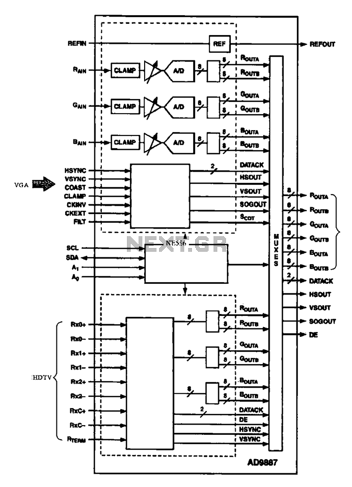
The AD9887, a commonly used video A/D converter for liquid crystal televisions, is capable of converting analog red, green, and blue (R, G, B) signals into digital signal outputs. The AD9887 is a high-performance analog-to-digital converter (ADC) specifically designed for...
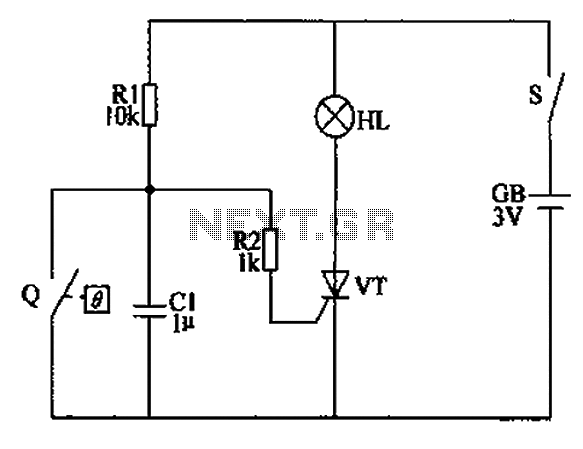
The automatic anti-frost crop controller circuit comprises an electric contact mercury thermometer (Q), a control circuit, ignition devices, and other components. The electric contact mercury thermometer features two platinum electrodes; one acts as a contact electrode inserted at the...
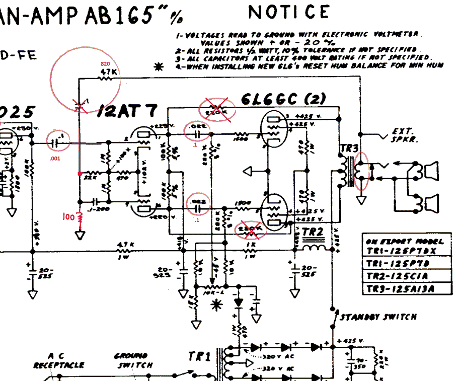
The Fender Bassman is a legendary guitar amplifier recognized by both guitar and bass players. Introduced in 1951, it was primarily aimed at bass guitar players and marketed as a bass amplifier for the Fender Precision Bass guitar, the...
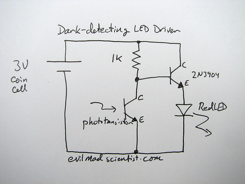
How can an LED be activated in low light conditions? This scenario, often referred to as the "nightlight problem," is applicable in various situations such as emergency lights, street lights, and even computer keyboard backlights. There are numerous solutions...
Many beginners trying out their skill with QRP TX for the first time have to overcome many problems before they are able to come on the air. One usual complaint is that everything is working fine, but the signal...