
AD converter AD9887 circuit

The AD9887 is a high-performance analog-to-digital converter (ADC) specifically designed for video applications, particularly in liquid crystal display (LCD) televisions. Its primary function is to convert the analog RGB signals, which are typically generated by video sources, into a digital format suitable for processing by digital circuits or microcontrollers.
The chip operates with a high sampling rate, ensuring that the conversion maintains the integrity of the video signal and minimizes latency. The architecture of the AD9887 includes a high-speed sample-and-hold circuit, which captures the analog input signals with precision. Following this, the signals undergo quantization through a multi-bit ADC, which translates the continuous analog signals into discrete digital values.
The output of the AD9887 is typically formatted in a standard digital interface, such as RGB or YCbCr, allowing for easy integration with various digital display systems. The device also features programmable gain amplifiers (PGAs) for each color channel, enabling the adjustment of signal levels to optimize the conversion process and accommodate different input signal amplitudes.
Additionally, the AD9887 may include integrated functions such as synchronization signal extraction and support for various color spaces, enhancing its versatility in diverse video applications. The chip is often housed in a compact package, making it suitable for integration into space-constrained designs typical of modern LCD televisions.
In summary, the AD9887 serves as a critical component in the video processing chain, facilitating the transition from analog to digital formats while maintaining high fidelity and performance in liquid crystal television systems. As shown in the commonly used liquid crystal television video A/D converter AD9887, the chip can be analog R, G, B signal is converted into a digital signal output.
Related Circuits
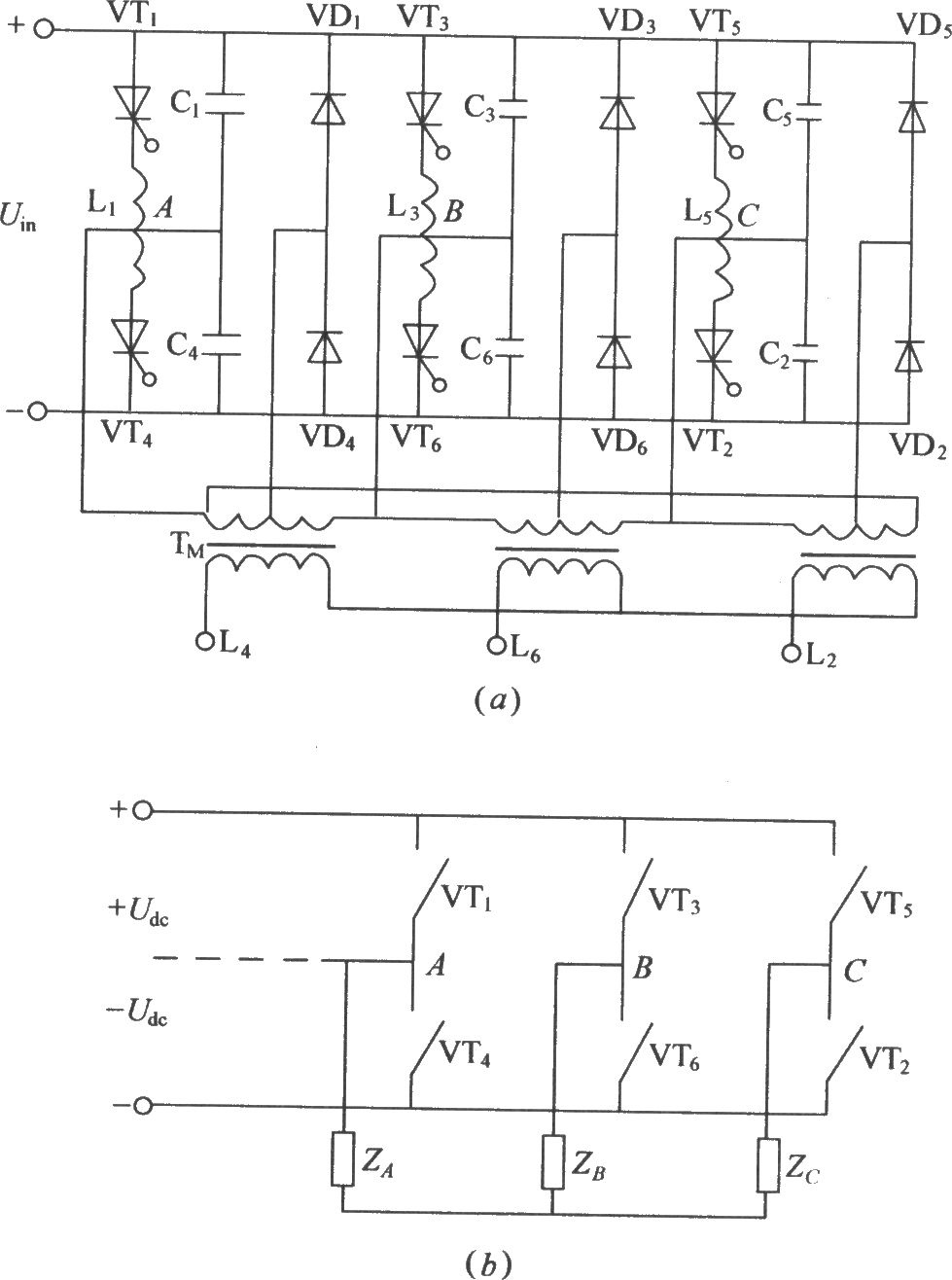
The figure illustrates a traditional three-phase bridge inverter circuit. Components VT1 to VT6 represent thyristors, while L1 to L6 are commutation reactors. Capacitors C1 to C6 serve as commutating capacitors, and the thyristor shut-off circuit is composed of two...
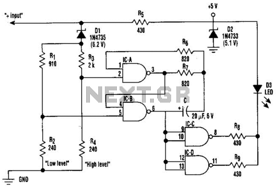
This circuit displays three voltage levels: normal (11 to 15 V), high (greater than 15 V), and low (below 11 V). When the voltage is low, the LED illuminates steadily. In the normal voltage range, the LED remains off....

Figure 1-122 is a dedicated high-fidelity surround sound processing integrated circuit (IC) TDA3810 circuit that manages surround sound. The stereo signal is processed through input coupling capacitors C1 and C2. The internal buffer amplifier handles the left and right...
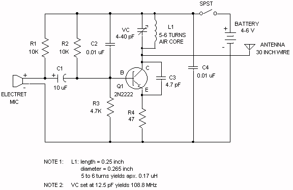
The electret microphone operates with a current of 200 µA, which varies by ±3 µA in response to sound waves. This variation results in a voltage of 2V across resistor R1 and 4V across the microphone. As sound waves...
This is an enhanced infrared (IR) remote control extender circuit. It features high noise immunity, resistance to ambient and reflected light, and an extended range of approximately 7 meters from the remote control to the extender circuit. It is...
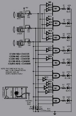
This circuit is capable of sensing eight colors: blue, green, and red (primary colors); magenta, yellow, and cyan (secondary colors); along with black and white. It is designed based on the principles of optics and digital electronics. The object...