
Another Small Single Chip FM Transmitter
This monophonic FM transmitter is designed to operate on a single frequency, making it suitable for various applications such as transmitting audio signals over short distances. The circuit typically consists of a few key components: an oscillator, a modulator, and an amplifier.
The oscillator generates a carrier frequency, which is modulated by the audio input signal to create the FM signal. This modulation is achieved using a component such as a varactor diode or a transistor configured to vary the frequency based on the amplitude of the audio signal. The output of the oscillator is then fed into a buffer amplifier to ensure that the signal can drive the next stage without distortion.
The circuit may also include passive components like resistors and capacitors to set the frequency of oscillation and to filter the output signal. An antenna is connected to the output stage to radiate the modulated signal into the air, allowing it to be received by standard FM radio receivers.
Power supply considerations are also crucial; the circuit typically operates at low voltage, often from a battery or a small power adapter, ensuring portability and ease of use. Proper layout and component selection are essential to minimize interference and optimize performance, particularly in a compact design.
Overall, this monophonic FM transmitter circuit provides a simple yet effective solution for wireless audio transmission, making it an excellent choice for hobbyists and educational projects.This FM transmitter circuit is small, similar to our previous single chip FM? transmitter, but this FM transmitter is monophonic. You can see in the circuit`s. 🔗 External reference
Related Circuits

This circuit includes automatic exit and entry delays, a timed bell cut-off, and a system reset feature. It is designed to support both normally-open and normally-closed switches and can accommodate standard input devices such as pressure mats, magnetic reed...
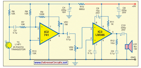
This circuit generates audio musical notes that can be heard from a distance of up to 10 meters. The circuit is divided into two parts: an infrared (IR) music transmitter and a receiver. The circuit operates on the principle of...
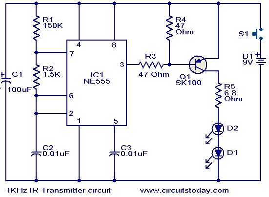
This circuit was designed in response to a request for a 1 kHz infrared (IR) transmitter circuit suitable for remote control applications. It is intended to serve as a low-power IR transmitter with an operating frequency of 1 kHz,...
The circuit of an FM Tracking Transmitter Circuit or Remote Control Transmitter Circuit is explained using a 555 IC and 2N4392 transistors. The FM Tracking Transmitter Circuit utilizes a 555 timer integrated circuit (IC) configured in astable mode to generate...
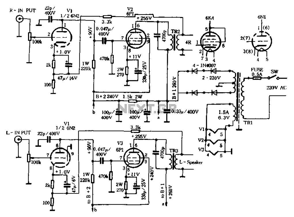
The original radio circuitry has been transformed into a block diagram representation. The electrical schematic is illustrated in Figure 1-27, which depicts a typical single-tube amplifier of Group A. One figure represents the audio amplifier circuit for the original...

The Intan Technologies RHA2116 is a 16-channel integrated amplifier array that requires only three external resistors to set the amplifier bandwidth, two capacitors for power supply smoothing, and occupies one square centimeter of board area. The digital-output and analog-output...