
Anti-RF filtered power supply 12-14 Volt / 3A

Parts list:
R1 = 220 Ohm 1/4W
R2 = 1.8 KOhm 1/4W
R3 = 330 Ohm 1/4W
P1 = 100 Ohm
C1, C2, C3 = 4,700uF/25V
C4 = 100pF ceramic
C6 = 100uF/25V electrolytic
D1, D2, D3, D4 = 1N5400-4 or RAX GI 837U
F1 = 5A
IC1 = LM350K
The power supply circuit is a regulated DC supply specifically tailored for RF applications. It utilizes a transformer rated at 220V/18V and 3A, which steps down the high voltage AC to a lower voltage suitable for the circuit. The input from the transformer is connected to the first two pins of the LM350K voltage regulator, which is the central component of this power supply.
The LM350K is a versatile adjustable voltage regulator capable of delivering up to 3A of output current. It is essential to attach a sufficient heatsink to the LM350K to dissipate heat generated during operation, particularly when the current approaches its maximum rating. Overheating can lead to thermal shutdown or damage to the regulator.
The circuit features several passive components that contribute to its performance. Resistors R1, R2, and R3 are used to set the output voltage and stabilize the operation of the LM350K. Capacitors C1, C2, and C3, each rated at 4,700uF and 25V, serve as bulk filtering capacitors, smoothing out the output voltage and reducing ripple. The 100pF ceramic capacitor C4 is likely used for high-frequency stability, while the 100uF electrolytic capacitor C6 provides additional filtering.
Diodes D1 through D4, which can be either 1N5400-4 or RAX GI 837U, are employed for rectification and protection against reverse polarity. They ensure that current flows in the correct direction and safeguard the circuit components from potential damage. The fuse F1 rated at 5A protects the power supply from overcurrent conditions, ensuring safe operation.
Overall, this power supply design is straightforward yet effective for powering RF equipment, providing a stable and clean DC output necessary for optimal performance in sensitive applications.This power supply is dedicated for use with rf equipments like, linear amplifiers, transmitters, receivers, and in every application that clean an-noisy signal is required. The circuit is very simple and you can drive it with a 220V/18V/3A transformer at the pins 1and 2. The regulator used here is the LM350K and make sure you place a good heatsink to it because it gets too hot if current gets near to 3A. Parts list: R1 = 220 Ohm 1/4W R2 = 1,8 KOhm 1/4W R3 = 330 Ohm 1/4W P1 = 100 Ohm C1,C2,C3 = 4.700uf/25V C4 = 100pf ceramic C6 = 100uf/25V electrolitic D1..4 = 1N5400-4 or RAX GI 837U F1 = 5A IC1 = LM350K
Related Circuits
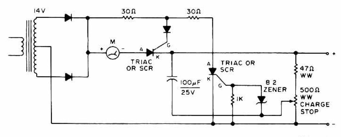
The charging circuit features adjustable voltage output settings, allowing for regulation of the charging voltage supplied to the battery. The use of a potentiometer facilitates precise voltage management, with adjustments possible down to the millivolt range. Refer to the...
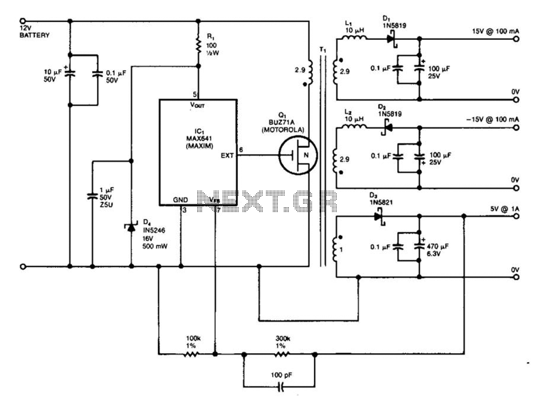
IC1 is a switching regulator that generates a 45-kHz signal to drive the gate of MOSFET Q1. Diodes D1, D2, and D3 are Schottky diodes. The 5-V output is monitored as a reference; feedback to the chip disables the...
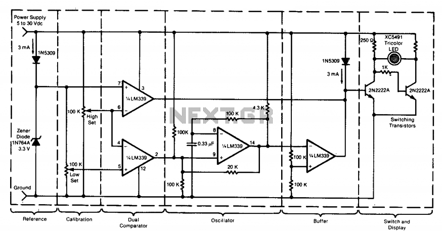
This circuit utilizes a tricolor LED display to signify acceptable and unacceptable output voltages. One LED indicates the upper voltage limit, while another indicates the lower voltage limit. When the monitored voltage exceeds the maximum set point, the LED...
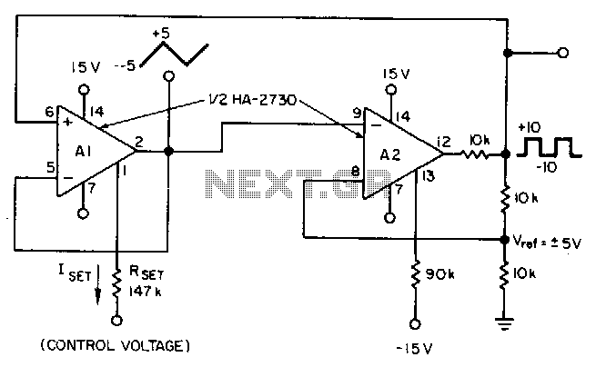
This circuit utilizes a programmable operational amplifier, specifically the HA2730, which is a two-amplifier monolithic chip featuring independent programming ports for each amplifier. The parameters of the amplifiers, including the slew rate, vary linearly based on a set current....
The first application has to be a stereo power amp, since that's what I built using two prototype modules. The reasons for this choice are twofold - a good high powered stereo amp is always useful, and it was important...
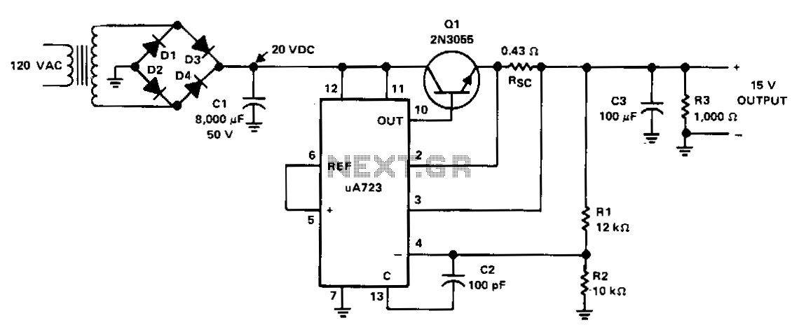
The power supply receives +20 VDC from the rectifier/filter section. This voltage is applied to pins 11 and 12 of the uA723 voltage regulator, as well as to the collector of the 2N3055 series-pass transistor. The output voltage is...