
Charger circuit equipped with a regulator circuit output voltage Schematic Diagram

The circuit design incorporates a voltage regulator that ensures a stable output voltage suitable for charging various battery types. The potentiometer is connected in a voltage divider configuration, enabling fine-tuning of the output voltage. This flexibility is crucial for different battery chemistries, which may require specific charging voltages to optimize performance and longevity.
The input section of the circuit typically includes a transformer or an AC to DC converter to provide the necessary input voltage. Following this, a rectifier circuit converts the AC voltage to a pulsating DC voltage, which is then smoothed using capacitors to reduce ripple. The voltage regulator, often implemented using integrated circuits such as the LM317 or similar, maintains a constant output voltage despite variations in input voltage or load conditions.
Additionally, the circuit may include protection features such as fuses or diodes to prevent overcurrent situations and reverse polarity connections. An LED indicator can also be incorporated to show the charging status, providing visual feedback to the user.
Overall, this adjustable voltage charger circuit is designed for efficiency and reliability, ensuring safe and effective charging of batteries across a range of applications.The circuit charger is equipped with voltage output settings, so that we can regulate how much voltage to charge the battery. And the settings using the potentio making it easier for us managing voltage up to a mV. See charger circuit below : You are reading the Circuits of Charger circuit equipped with a regulator circuit output voltage And this
circuit permalink url it is 🔗 External reference
Related Circuits
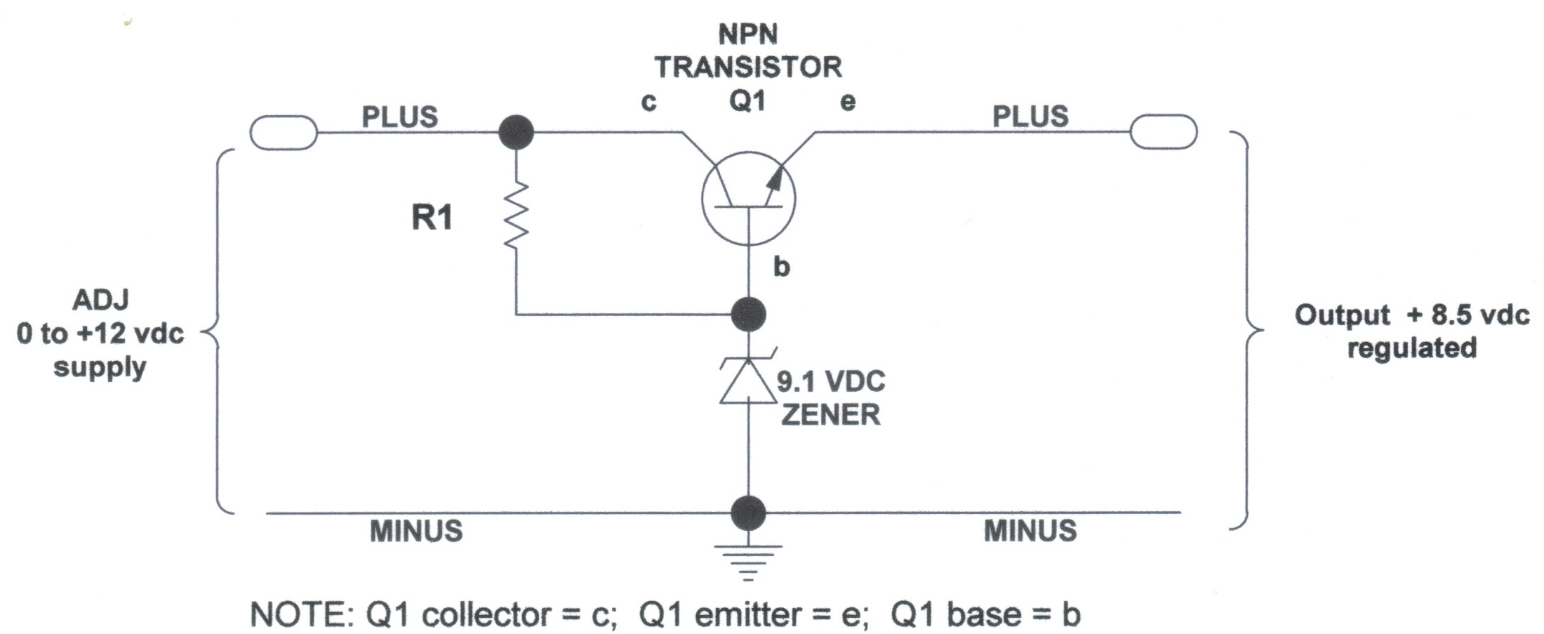
DC Voltage Regulator (NPN & Zener Regulator) There are instances where it is handy to have a regulated DC voltage power supply for use on your model. A DC voltage regulator is an essential component in electronic circuits that provides...
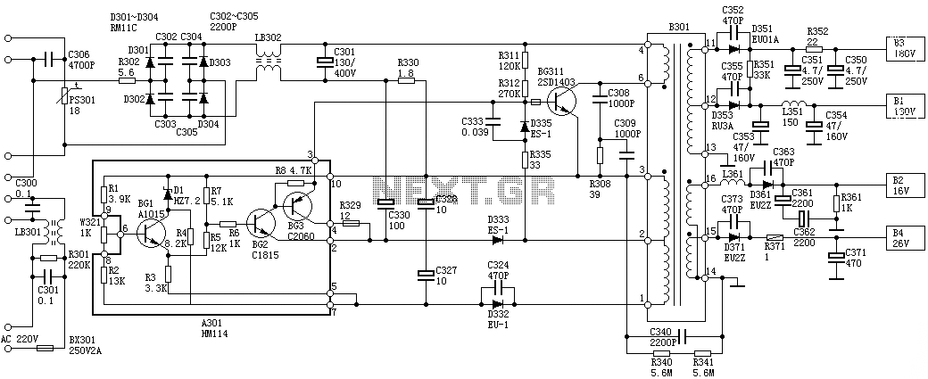
Oscillation: The positive terminal voltage of C310 is approximately 300V. The resistors R311 and R312 are connected to the switch BG311 at the B pole, while the B301 winding via the switching transformer (4) and (6) is connected to...
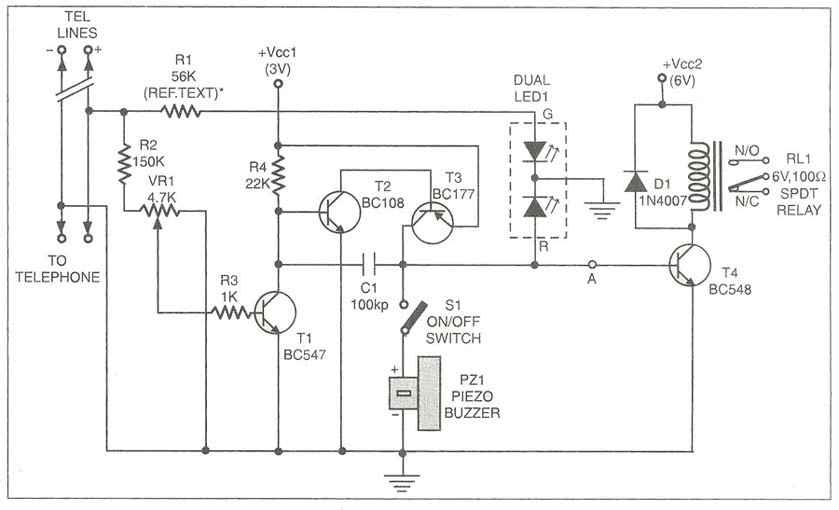
Multipurpose circuit for telephone. This add-on device for telephones can be connected in parallel to the telephone instrument. The circuit provides audio-visual indication of on-hook. This multipurpose circuit serves as an enhancement for standard telephone systems by providing both audio...

A constant voltage battery charger is required, with an output of 44V and a maximum current of 1A. This charger will be integrated into the battery compartment of an e-bike and will maintain a permanent connection to the three...
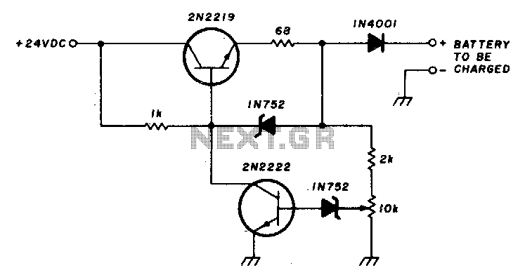
This circuit charges a battery at a rate of 75 mA, allowing the battery to remain in the charger indefinitely until fully charged. Once the battery reaches its full charge, the circuit reduces the current to a trickle rate....
A field effect transistor (FET) voice amplifier has a low input impedance, approximately 1 kΩ, requiring the signal source to provide a constant current signal for operation. Unlike bipolar transistors, FETs are voltage-controlled devices that draw minimal current at...