
anti theft security for car audios

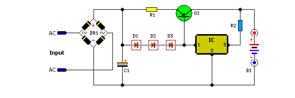
The circuit described operates on a 12V DC supply sourced from a car battery, utilizing various components to create a security system for the car audio unit. The initial state of the system is indicated by LED1, which confirms that the circuit is in standby mode when switch S1 is closed. The optocoupler IC1 plays a critical role in isolating the control signals from the car audio system, ensuring that the primary circuit remains inactive until a disruption is detected.
In the event of an unauthorized removal of the car audio, the circuit's response is triggered by the loss of the ground connection at the optocoupler's cathode. This disconnection allows the oscillator circuit, constructed around gates N2 and N3, to activate. The oscillator generates a square wave signal that drives transistor T2, which in turn controls relay RL1. The relay's contacts can be configured to activate various alarm systems, such as beepers or indicators, depending on user preference.
Capacitor C2 is integral to determining the timing characteristics of the relay operation. By selecting different capacitance values, the user can customize the duration for which the relay remains energized, thus tailoring the alarm response to their specific needs. For instance, a 100 µF capacitor results in a balanced 5 seconds of activation followed by 5 seconds of deactivation.
The circuit also incorporates a differentiating circuit formed by capacitor C1 and resistor R5, which generates a short pulse when the ignition key is turned off. This pulse momentarily turns on transistor T1, allowing the buzzer to sound briefly, providing an audible indication of the ignition status. The timing of this buzzer activation can be adjusted by varying the values of C1 and R5, enabling further customization of the alert features.
In summary, the described circuit effectively combines a security mechanism with customizable timing features to protect the car audio system against unauthorized removal. Proper installation of the LED and buzzer on the dashboard, along with strategic placement of switch S1, enhances the usability and effectiveness of the system.When 12V DC from the car battery is applied to the gadget (as indicated byLED1) through switch S1, the circuit goesinto standby mode. LED insideoptocoupler IC1 is lit as its cathode terminalis grounded via the car audio (amplifier)body.
As a result, the output atpin 3 of gate N1 goes low and disablesthe rest of the circuit. Whenever an attempt is made to removethe car audio from its mounting bycutting its connecting wires, theoptocoupler immediately turns off, as itsLED cathode terminal is hanging. As aresult, the oscillator circuit built aroundgates N2 and N3 is enabled and it controlsthe on`/off` timings of the relay viatransistor T2.
(Relay contacts can be usedto energise an emergency beeper, indicator, car horns, etc, as desired. ) Different values of capacitor C2 givedifferent on`/off` timings for relay RL1 tobe on`/off`. With 100 F we get approximately5 seconds as on` and 5 seconds asoff` time. However, when one switches off the ignitionkey, the supply to the car audio isalso disconnected. Thus the output of gateN4 jumps to a high` state and it providesa differentiated short pulse to forward biastransistor T1 for a short duration. (Thecombination of capacitor C1 and resistorR5 acts as the differentiating circuit. ) This on` periodof buzzer can bevaried by changingthe values ofcapacitor C1and/or resistorR5. After construction, fix theLED and buzzerin dashboard asper your requirementandhide switch S1in a suitable location.
🔗 External reference
Related Circuits
Unlike many units, this battery charger continuously charges at maximum current, tapering off only near full battery voltage. In this unit, the full load. This battery charger is designed to operate with a continuous charging mechanism, maintaining the maximum current...
Anti-log or exponential generation involves rearranging logarithmic circuitry. The circuit diagram below illustrates the relevant circuitry. Anti-logarithmic or exponential circuits are essential in various applications, particularly in signal processing and analog computing. These circuits typically utilize operational amplifiers (op-amps) configured...

The Unmanned Ground Vehicle (UGV), also referred to as the Spycar project, is a radio-controlled four-wheeled platform capable of six different motions. This vehicle can be equipped with a wireless camera, allowing for video feedback to be transmitted to...
The TL494 controls a car's audio inverter power supply, which is a high-fidelity audio power supply designed for custom vehicles. It operates reliably without the need for adjustments according to the provided circuit diagram. The TL494 is a versatile integrated...
This circuit was requested by several correspondents. Its purpose was to obtain more power than the siren circuit already available on this website (One-IC two-tones Siren) and to avoid the use of ICs. A complementary transistor pair (Q2 &...
This sensor circuit was designed to assist in parking a car near a garage wall while reversing. LED D7 lights up when the distance from the bumper to the wall is approximately 20 cm. LEDs D7 and D6 illuminate...