
12 Volt Car Battery Charger Circuit Schematic

This battery charger is designed to operate with a continuous charging mechanism, maintaining the maximum current output throughout the majority of the charging cycle. As the battery approaches its full voltage capacity, the charging current gradually decreases, a process known as "tapering off." This method is beneficial for ensuring that the battery receives an adequate charge without the risk of overcharging, which can lead to battery damage or reduced lifespan.
The circuit typically consists of several key components, including a power supply, a current regulation module, and a voltage sensing circuit. The power supply provides the necessary voltage and current to begin the charging process. The current regulation module ensures that the output current remains at the maximum allowable level for the battery being charged, which is critical for efficient charging.
As the battery voltage rises, the voltage sensing circuit continuously monitors the battery's voltage level. Once the voltage reaches a predetermined threshold, the current regulation module begins to reduce the output current. This tapering effect helps to prevent excessive heat generation within the battery and enhances safety during the charging process.
The charger may also include additional features such as temperature compensation, which adjusts the charging parameters based on the battery temperature to optimize performance and safety. Furthermore, an LED indicator may be integrated into the design to provide visual feedback on the charging status, indicating when the battery is charging, fully charged, or if there is an error in the charging process.
Overall, this battery charger design emphasizes efficiency and safety, making it suitable for various applications where reliable battery charging is essential.Unlike many units, this battery charger continuously charges at maximum current, tapering off only near full battery voltage. In this unit, the full load.. 🔗 External reference
Related Circuits
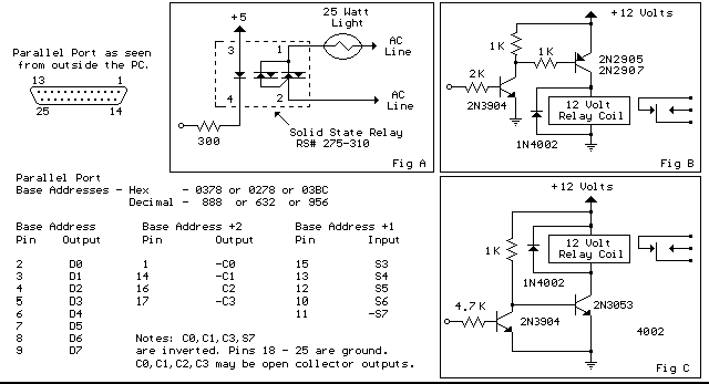
Below are three examples of controlling a relay from the PC's parallel printer port (LPT1 or LPT2). Figure A shows a solid-state relay controlled by one of the parallel port data lines (D0-D7) using a 300-ohm resistor and a...
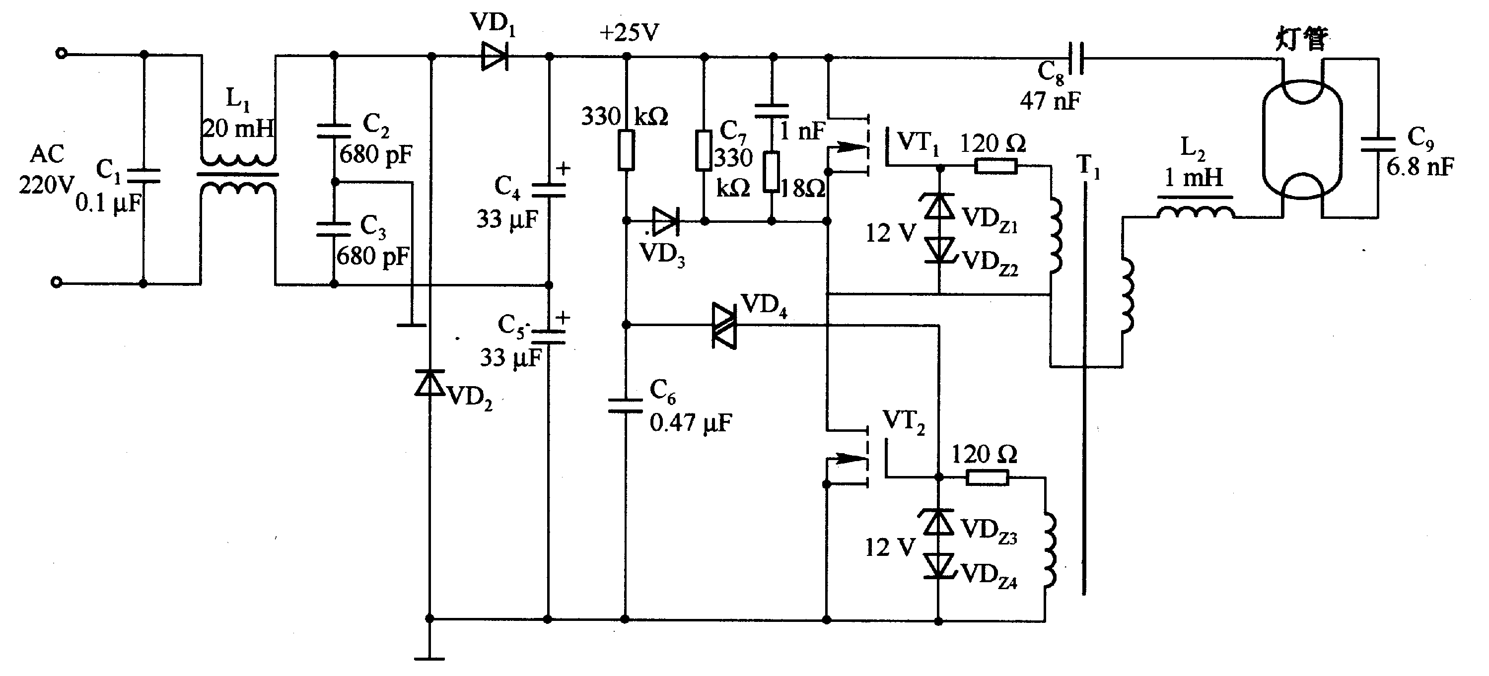
A fluorescent tube is connected in an LC resonant circuit consisting of inductor L2 and capacitor C9. The bidirectional breakdown diode VD4 initiates the starting circuit. When AC power is applied, the gate potential of transistor VT2 increases due...
This circuit can be utilized as a replacement for the single current-limiting resistor typically found in low-cost battery chargers. The alternative presented here is advantageous because it prevents the premature failure of nickel-cadmium (NiCd) batteries, which often occur after...
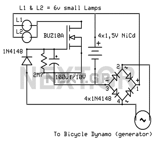
That Circuit is an advanced bicycle lighting system which will power your lights and also charge four NiCd batteries while you running in the streets, for keeping the lights on while the bicycle is stopped. Its fully automated without...

A voltage-controlled oscillator using the NE555. This circuit is commonly referred to as a voltage-to-frequency converter because the output frequency is altered by varying the input voltage. As previously noted, pin 5 serves as the voltage control terminal, which...

The input capacitor is used for low-frequency cut-off, with a standard value of 0.1 µF, resulting in a cut-off frequency of approximately 16 Hz. The input capacitor plays a critical role in electronic circuits, particularly in signal processing and audio...