
swr metering circuit and ssb transceiver 80m 40m boster filter if radio

The broadband QRP SWR (Standing Wave Ratio) metering circuit serves as an essential tool for amateur radio operators using low-power (QRP) transmitters. This circuit is designed to provide real-time feedback on the impedance matching between the antenna and the transmitter, which is crucial for efficient operation and to prevent damage to the transmitter.
The schematic includes a momentary double-pole double-throw (DPDT) switch that, when pressed, activates the SWR measurement process. The LED indicator is used to visually represent the SWR level: a dim LED indicates a good match (minimum SWR), while a bright LED signals a poor match (high SWR). This feedback allows operators to fine-tune the antenna tuner by adjusting its capacitors.
Key components of the circuit may include resistors, capacitors, and diodes configured to form a voltage divider that translates the RF power levels into a readable format for the LED. The design should ensure that the circuit operates across a broad frequency range, accommodating various amateur radio bands. Additionally, attention must be paid to component ratings to handle the power levels typical in QRP operations without distortion or damage.
Overall, this broadband QRP SWR metering circuit is a valuable addition to any QRP antenna tuner, providing a simple yet effective means of optimizing antenna performance.A schematic diagram for a broadband QRP SWR metering circuit for use in a QRP antenna tuner. One could simply hold a momentary DPDT switch down and watch the LED while tuning the capacitors of the antenna tuner for minimum or zero light. 🔗 External reference
Related Circuits
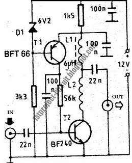
This design presents a simple antenna amplifier electronic circuit project, which can be utilized based on the provided circuit diagram. The antenna amplifier operates effectively within a frequency range of 1 to 300 MHz. It is suitable for high...
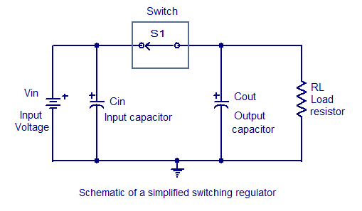
Switching regulators operate by drawing small amounts of energy from the input source and transferring it incrementally to the output. This is achieved using an electronic switch, which functions at a predetermined frequency, acting as a gate between the...
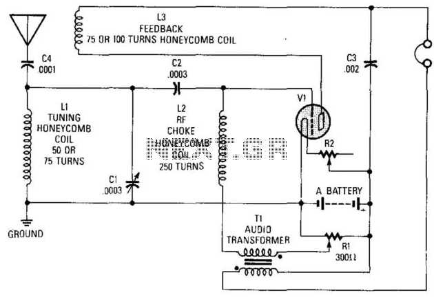
This circuit was utilized in the early days of radio for signal reception. It can employ nearly any battery-operated triode, such as a type 30. The "A" battery provides 3 V, R2 is a 100-ohm rheostat, and the coils...
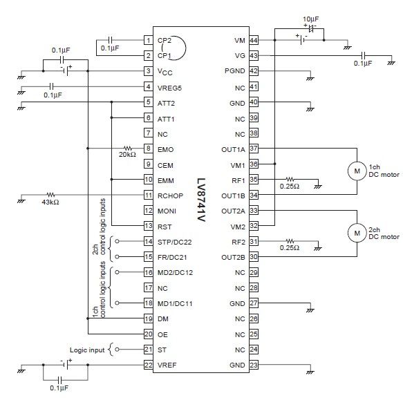
The circuit diagram illustrates an electronic project that requires a few external electronic components. The PWM current-control stepping motor driver IC can provide a maximum output current of up to 1.5 amperes. The configuration settings for the PWM current-control...
In many countries, it is now mandatory or at least recommended to have a rear fog light on a trailer. There is an additional requirement that when the trailer is connected to the vehicle, the rear fog light of...

An ultrasonic cleaner is effective for cleaning specific items. This circuit employs a microcontroller to manage timing and provide a digital display, although a basic oscillator can be utilized if preferred. RESL and RES2 are piezoelectric transducers activated by...