
Application of the differential amplifier circuit in a simple small oscilloscope

The differential amplifier circuit is a crucial component in the design of a simple small oscilloscope. This circuit is designed to amplify the difference between two input voltage signals while rejecting any common-mode signals, making it ideal for applications where precision and noise immunity are essential.
In the context of a small oscilloscope, the differential amplifier can be utilized to measure voltage signals from various sources, such as sensors or other electronic circuits. The circuit typically consists of operational amplifiers (op-amps) configured in a differential mode, which allows for high input impedance and low output impedance. This configuration ensures that the oscilloscope can accurately capture and display the voltage waveform without loading the source.
The differential amplifier circuit includes resistors that set the gain of the amplifier, allowing for adjustments based on the specific requirements of the measurement. The output of the differential amplifier feeds into the analog-to-digital converter (ADC) of the oscilloscope, converting the amplified analog signal into a digital format for processing and display.
Additionally, the small oscilloscope may incorporate features such as a display unit, control buttons for adjusting time base and voltage scale, and power supply circuitry to ensure stable operation. The overall design emphasizes portability and ease of use, making it suitable for both educational purposes and field applications. By effectively utilizing the differential amplifier, the small oscilloscope can provide accurate waveform representations, facilitating analysis and troubleshooting in various electronic systems.Application of the differential amplifier circuit in a simple small oscilloscope
Related Circuits
A buffer amplifier is necessary for a typical pH probe to isolate its source resistance, which ranges from 10^6 to 10^9 ohms, from the external circuitry. Such an amplifier is illustrated in the... The buffer amplifier serves a critical role...
Figure 1 illustrates an AND gate logic circuit with the logic expression P=A. Figure B depicts two photodiodes connected in series. When the input logic levels A=1 and B=1, the output P=1. Similarly, this configuration can be used to...
There are two types of solar automatic tracking controllers. One type utilizes a Schmitt trigger light control, which consists of a light sensor and a Schmitt trigger or monostable trigger. The second type employs two light sensors and two...
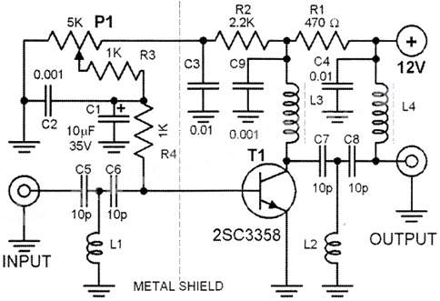
This wideband DTV UHF antenna TV amplifier provides a total gain ranging from 10 to 15 dB within the frequency domain of 400 to 850 MHz. The wideband DTV UHF antenna TV amplifier is designed to enhance signal strength for...
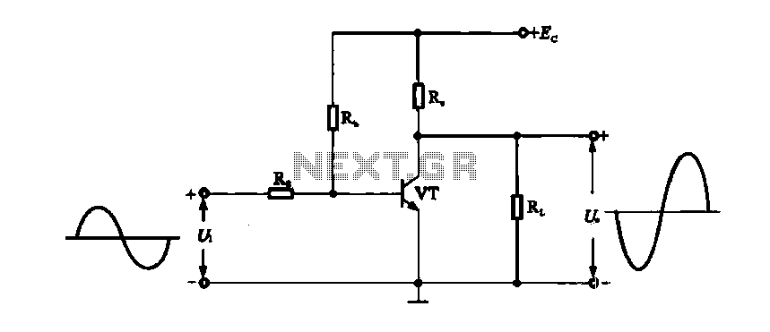
A DC-coupled single-tube amplifier is a circuit that utilizes a single transistor to amplify DC signals. This configuration primarily consists of a transistor, bias resistors, and minimal coupling capacitors. The absence of coupling capacitors allows the DC operating states...
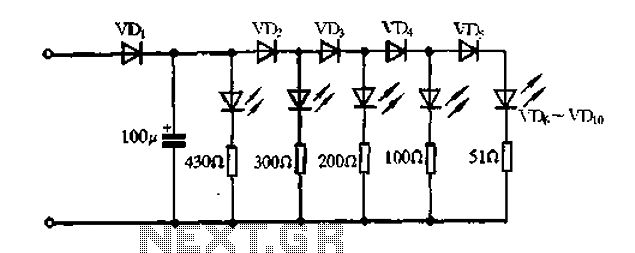
A passive light-emitting diode output level indication circuit. This circuit utilizes a light-emitting diode (LED) to provide a visual indication of the output level from a given source. The design is characterized by its passive nature, meaning it does not...