
Arduino Audio DAC Options

Of all the various methods of sound generation the DAC method seems most versatile to me. As mentioned before DAC is a common short name for Digital to Analog Converter. Basically a binary/digital value is converted to an analog/voltage value. An 8-Bit DAC would convert a binary value in the range of 0 to 255 into an analog voltage from 0 to 5V. The exact voltage range of the conversion is dependent on the DAC configuration but for most things we will play with, 0 to 5V will work.
Since analog signals, especially sound, needs to swing plus and minus around 0V we often bias the DAC so that mid scale is considered 0V. If the DAC outputs from 0 to 5V then we usually bias the signals so that 2. 5V is translated to 0V. If we generate our output signals so that half scale is 2. 5V then we can AC couple the output to get a +/- 2. 5V swing. The half scale biasing may be a bit confusing but really it`s easy once you get the general idea. We just call 1/2 scale zero so that any numbers above 1/2 are positive and below are negative. For an 8 bit converter we can use the MSB as a sign bit to make this happen. Consider that decimal 128 is 10000000 in binary. Note that the MSB is set and this is basically half scale of the possible 0-255 range. Think of the MSB as a sign bit, it`s one for positive values and 0 or negative. Using this 1/2 scale bias we can convert any digital number that might represent sound data into a value to load into a DAC.
The first step is to convert the number into the range of +/-127 and add 128 to it. In this example that will make the analog version swing from 0 to 5V with the original zero point set at 2. 5V. We can remove that 2. 5V bias in the hardware with a simple series capacitor. The series capacitor is not even needed in most applications. For example I use my sound card line input to do these experiments. This input has a series capacitor. The series capacitor is used to provide A/C coupling. This just means that the signal swings evenly around 0V. The +/- voltage swing is enforced about the average DC level by the capacitor. Of course there is a frequency response for the series capacitor but the value of the capacitor is usually high enough so that it will not be a problem for audio frequency ranges.
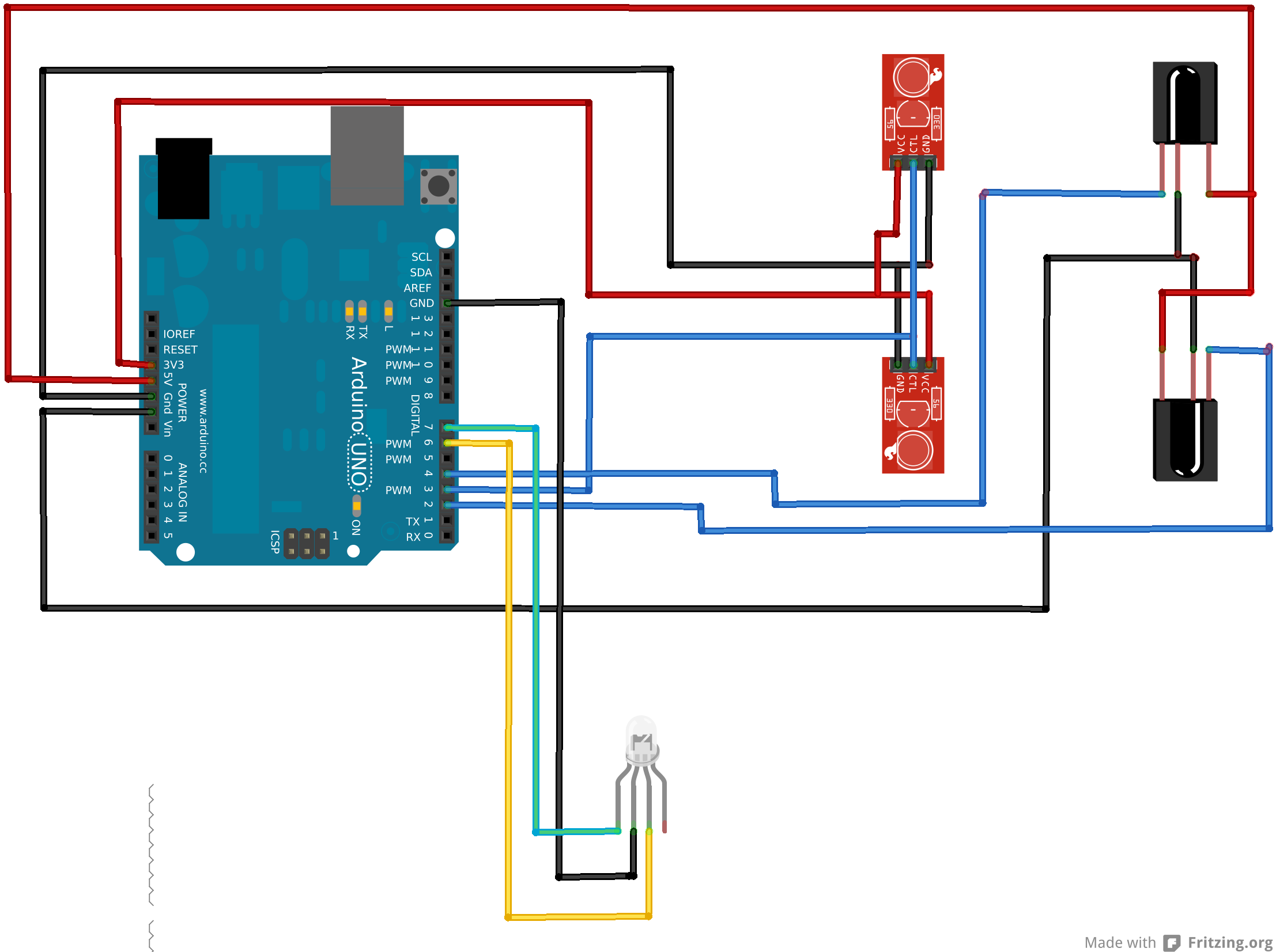
This diagram shows the circuit I used between the various DAC outputs and my PC sound card input. The series resistor and capacitor to ground form a simple filter to knock off the high frequency noise caused by the DAC switching instantly between the voltage values. It removes the high frequency components. The 100K variable resistor (POT) lets me adjust the output voltage level for each DAC. A line input should be kept in the 1V Peak to Peak range or +0. 5 to -0. 5 range. Since the sound card has A/C coupling I only need to adjust the amplitude using this POT as a voltage divider.
Also note that I connected both the right and left side inputs to the filtered output. There is no additional parts required to implement the PWM sound output. Michael Smith`s PWM code generates PWM at about 60KHz. This high frequency is easily filtered with the filter described above. You really don`t even have to have this filter as the sound card has input filters. Even if you wanted to drive a speaker, you would not need to f 🔗 External reference
Related Circuits
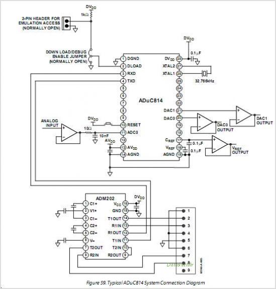
The ADUC816 is a complete smart transducer front-end that integrates two high-resolution sigma-delta ADCs, an 8-bit microcontroller unit (MCU), and program/data Flash EEPROM memory on a single chip. This low-power device accepts low-level signals directly from a transducer. The...
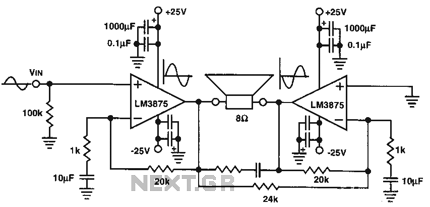
The audio power amplifier delivers 80W of audio power to an 8-ohm load. The LM3875 integrated circuit (IC) requires adequate cooling. It is important to note that in the bridge amplifier configuration, the two connected speakers will produce heat. The...
This is a 25 Watt basic power amplifier designed to be relatively easy to build at a reasonable cost. It offers better performance than standard STK module amplifiers commonly found in mass-market stereo receivers. The original design was created...
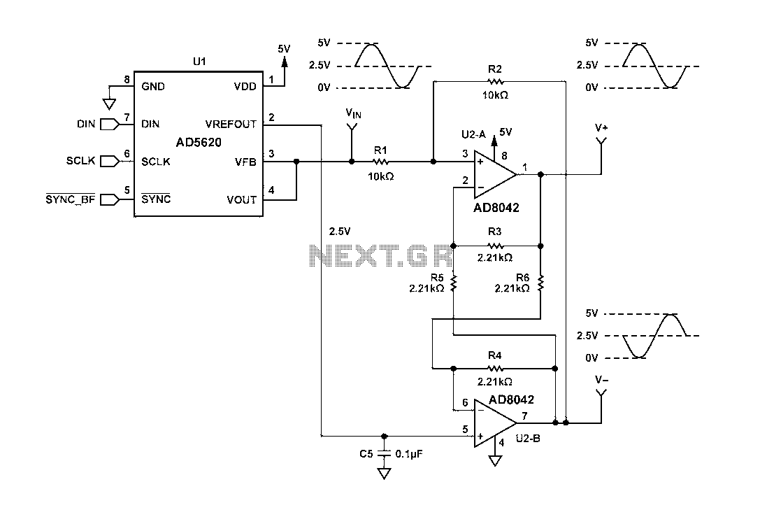
Figure 1 illustrates a circuit that utilizes a single +V power supply and a voltage output Digital-to-Analog Converter (DAC) known as the AD5620. The DAC is controlled via an SPI port, with its output ranging from 0 V to...
An Arduino Uno is connected to two infrared (IR) transmitters and their respective receivers. When one of the receivers detects a beam break, a strand of LEDs displays a pattern. While this setup functions correctly in principle, an issue...
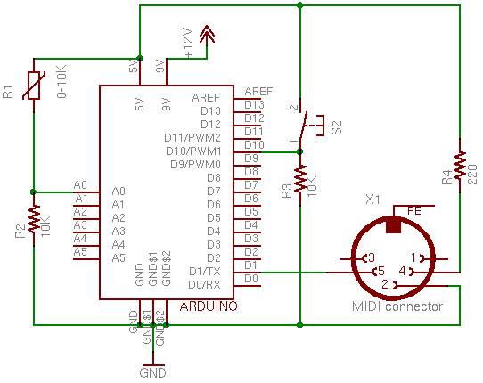
This page covers only the details of MIDI communication on the Arduino module. For a more general introduction to MIDI on a microprocessor, see the MIDI notes on Tom's physical computing site. MIDI, the Musical Instrument Digital Interface, is...