
MIDI Output with Arduino


The described circuit utilizes an Arduino module to facilitate MIDI communication, which is essential for interfacing with various musical devices. The MIDI protocol operates over a serial communication interface, typically using a 5-pin DIN connector for traditional setups, or USB for modern devices. In this implementation, the Arduino serves as a MIDI controller, capable of generating MIDI messages based on user interactions.
The circuit includes both analog and digital sensors to enhance interactivity. The analog sensor may be a potentiometer or a photoresistor, which can vary its resistance based on physical changes, such as light intensity or user adjustments. The digital sensor could be a push button or a toggle switch, providing discrete input to trigger specific MIDI events.
Despite the circuit's non-compliance with the MIDI specification, it remains functional with a variety of MIDI devices. This flexibility is important in practical applications where strict adherence to specifications may not be feasible. The circuit's design allows for straightforward integration with existing MIDI hardware, making it suitable for prototyping and experimentation.
To send MIDI messages, the Arduino must transmit specific byte sequences representing different MIDI commands. Each command is structured in a way that the first byte typically indicates the type of message (e.g., Note On, Note Off, Control Change), while subsequent bytes provide additional information, such as the note number and velocity. In this context, the Arduino can be programmed to format these bytes in hexadecimal or decimal format, facilitating easy interpretation and manipulation within the code.
In summary, this circuit exemplifies a practical approach to MIDI communication using Arduino, incorporating both analog and digital inputs for enhanced user interaction while maintaining compatibility with a wide range of MIDI devices. This versatility enables users to explore the capabilities of MIDI in various musical and creative applications.This page covers only the details of MIDI communication on the Arduino module. For a more general introduction to MIDI on a microprocessor, see the MIDI notes on Tom's physical computing site. MIDI, the Musical Instrument Digital Interface, is a useful protocol for controlling synthesizers, sequencers, and other musical devices.
MIDI devices are generally grouped in to two broad classes: controllers (i.e. devices that generate MIDI signals based on human actions) and synthesizers (including samplers, sequencers, and so forth). The latter take MIDI data in and make sound, light, or some other effect. This circuit doesn't actually match the MIDI specification, but it works with all the MIDI devices we've tried it with. This circuit includes an analog and a digital sensor to allow for physical interactivity, but those aren't necessary to send MIDI data.
Once you're connected, sending MIDI is just a matter of sending the appropriate bytes. The bytes have to be sent as binary values, but you can format them in your code as decimal or hexadecimal values. The example below uses hexadecimal format for any fixed values, and a variable for changing values. 🔗 External reference
Related Circuits
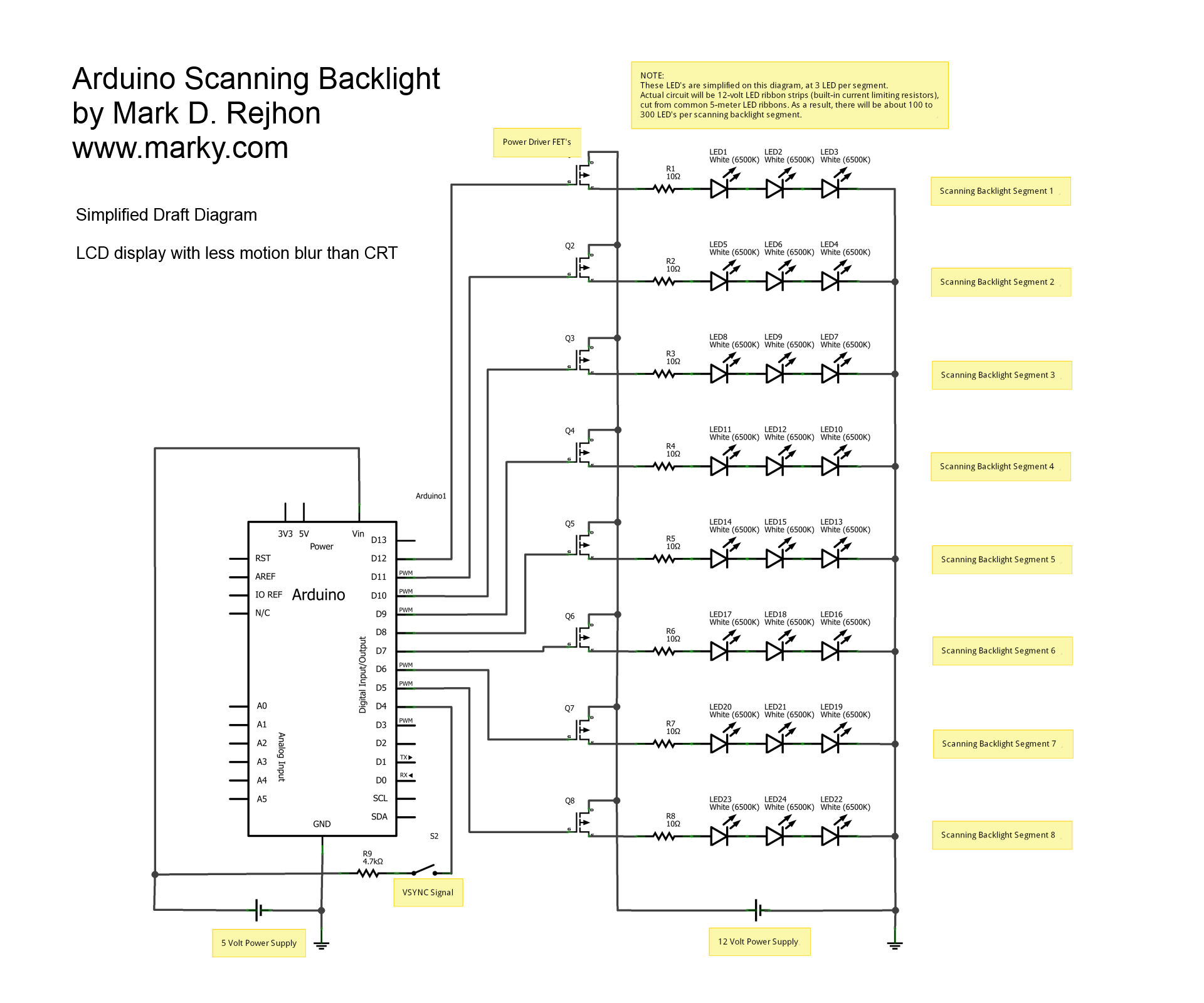
This is a simplified schematic diagram for a homemade scanning backlight driven by an Arduino, an open-source electronics prototyping platform. The Arduino monitors the VSYNC signal (input-lag compensated) and executes a backlight scanning sequence, using ultra-short strobes of super...
Here is a simple project that sends continuous or switch controller MIDI messages that correspond to the position of a potentiometer. Given a few parts and a cannibalized volume or wah-wah pedal, you can build this MIDI controller pedal...

Transmitter RF Output LED Indicator Circuit Diagram. This RF output detector circuit, which includes a visual indicator, can be useful for an RF application. The transmitter RF output LED indicator circuit is designed to provide a visual representation of the...
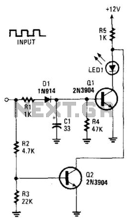
This circuit can be utilized to detect a stuck output or node in a circuit, or a loss of data or pulses. The pulse train charges capacitor C1 and biases transistor Q1 on, which illuminates the LED. If the...
The sustain pedal, also known as the damper pedal, sends a controller value of CC64 when operated. Pressing the pedal results in an output value of 127, while releasing it results in an output value of 0. Tone generators...

To achieve LED blinking at varying speeds, it is essential to modify the delay time for the LED's ON and OFF states. The fundamental approach involves changing the argument of the delay function based on time. Initially, the variable...