
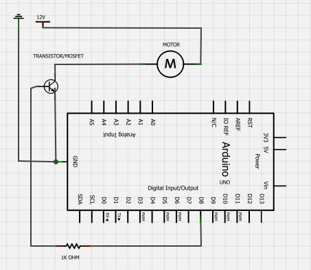
Arduino-based AVR High Voltage Programmer

The described Arduino-based AVR programmer utilizes high voltage (HV) programming techniques to reset microcontroller fuses, particularly the RSTDISBL fuse, which can disable the reset functionality of the ATmega microcontrollers. The circuit is designed around an Arduino board, which provides the necessary input/output capabilities to execute the HV programming protocol.
The main components of the circuit include the Arduino board, a perfboard for mounting, and a variety of passive and active components. The Arduino NG, Diecimila, or any compatible variant serves as the control unit, executing the HVFuse sketch that handles programming tasks. The perfboard is used to accommodate the various components while maintaining a compact design.
For user interaction, a pushbutton switch is included, referred to as the ‘go’ button, which initiates the programming process. An LED is incorporated into the circuit to provide visual feedback, indicating when it is safe to insert or remove the AVR microcontroller. The LED will illuminate to signal the user that the programming process is active and will turn off once the operation is complete.
The circuit employs a 2N3903 or similar NPN transistor to manage the high voltage required for programming. This transistor acts as a switch, allowing the Arduino to control the application of +12VDC to the target device safely. Additionally, a series of 1k ohm resistors are utilized throughout the circuit to protect the Arduino's I/O pins from potential short circuits or excess current, ensuring the longevity and reliability of the programmer.
The 28-pin socket is designed to accommodate the target AVR microcontroller, allowing for easy insertion and removal during the programming process. The design of the circuit takes into account the non-standard pin spacing of some digital lines (8-13), which may require drilling additional holes for proper header pin alignment.
Overall, this Arduino-based AVR programmer is a practical solution for restoring functionality to microcontrollers that have been rendered inoperable due to fuse settings, providing a straightforward and effective method for hobbyists and engineers alike.Fortunately, my trusty Arduino came to the rescue I created an Arduino-based AVR programmer that uses the high voltage programming mode and can fix pesky fuses like RSTDISBL. The Arduino has just enough IO to implement the entire HV protocol plus a go” button. So far I have only implemented setting LFUSE and HFUSE in software, but there is no reason why the code couldn’t be extended to support chip erase and programming the entire flash as well.
The fuse programming process is simple: Upload the HVFuse sketch to the Arduino, available for download here: HVFuse.pde Install the shield and apply +12VDC to the terminals on the left Wait for the red LED to turn on (if it isn’t already) Install the ATmega to be repaired Push the button As soon as the LED turns back on, the AVR is fixed and ready to be put back into service! Parts list: An Arduino NG, Diecimila, or compatible A piece of perfboard cut to size Header pins for the Arduino interface (note I had to drill some of the holes to get the headers to fit the nonstandard pin spacing for digital lines 8-13.
An LED which indicates when it is ok to insert/remove the AVR A 2N3903 or similar NPN transistor (2N2222, etc.) (20) 1k resistors these protect the Arduino from short circuits in case something goes wrong A pushbutton switch this is the ‘go’ button A 28 pin socket for the target AVR 🔗 External reference
Related Circuits

The PGA202 offset voltage correction circuit is designed to correct both input and output offset voltages. There are four different gain settings for the PGA202, which result in slight variations in input offset voltage. A 50k potentiometer is used...

This document illustrates the configuration of the high-precision, high-impedance OPA2111 amplifier. The total voltage circuit is designed for a magnification of Av = 10 (1 + 2R2 / R1), achieving a total gain of 1000 times. A gain stage...
The BC547 transistor has a maximum operating current of 100 mA and a maximum voltage rating of 65 volts. When oriented with the label facing the viewer, the three terminals from left to right are collector, base, and emitter....
STMicroelectronics introduces the STV0288, its latest DVB and DIRECTV QPSK digital receiver, which adds blind scan capability and DiSEqC 2.0 to the industry-leading STV0299 and provides a cost reduction path for new products. The STV0288 is a sophisticated digital receiver...
This circuit diagram is provided for those interested. It is a small circuit that takes an input of 1.5 volts and outputs 120 volts. The circuit in question is a voltage step-up converter, commonly referred to as a boost converter....
It is crucial to design the PCB layout correctly to enable seamless In-System Programming (ISP) of AVR microcontrollers. This guide addresses common issues encountered and provides typical AVR ISP circuit schematics. It focuses on Serial Programming, known as ISP,...