
STM1061 Low Power Voltage Detector

The STV0288 is a sophisticated digital receiver designed for DVB (Digital Video Broadcasting) and DIRECTV applications, utilizing QPSK (Quadrature Phase Shift Keying) modulation. This receiver enhances functionality by incorporating blind scan capability, enabling the automatic detection of available satellite channels without prior knowledge of their frequencies. This feature significantly simplifies the installation process and improves user experience.
In addition to blind scan, the STV0288 supports DiSEqC 2.0 (Digital Satellite Equipment Control), allowing it to manage multiple satellite dishes and LNBs (Low-Noise Block downconverters) effectively. This capability provides users with greater flexibility in satellite selection and system configuration, optimizing the overall performance of satellite reception systems.
The integration of these features into the STV0288 not only improves its operational capabilities but also offers a pathway for cost reduction in the development of new products. By leveraging existing technologies from the STV0299, the STV0288 presents a competitive solution for manufacturers looking to enhance their product offerings while managing production costs. This strategic advancement positions the STV0288 as a valuable component in the evolving landscape of satellite communication technologies.STMicroelectronics introduces the STV0288 its TM latest DVB and DIRECTV QPSK digital receiver, which adds blind scan capability and DiSEqC 2. 0 to the industry-leading STV0299 and provides a cost reduction path or new products. By STMicroelectronics 🔗 External reference
Related Circuits
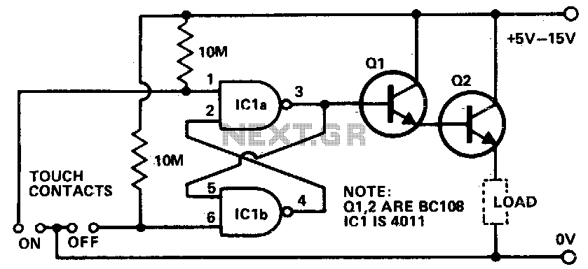
Touching the on contacts with a finger brings pin 3 high, turning on the Darlington pair and supplying power to the load (transistor radio, etc.). Q1 must be a high-gain transistor, and Q2 is chosen for the current required...
A live-line detector is a circuit designed to identify the presence of a live mains conductor through capacitive coupling between the live conductor and the detection circuit. The live-line detector operates on the principle of capacitive coupling, which allows it...
The current source IC Type LM334 is utilized in this specialized application, which features a minimal temperature coefficient and operates with a very low current draw of only 10 µA at room temperature. This current increases slightly with higher...
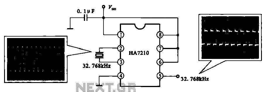
This circuit illustrates a 32.768 kHz micro-power clock oscillator, suitable for use in mobile phones, laptop computers, and home appliances. It generates a clock signal that can be utilized in various applications. The 32.768 kHz micro-power clock oscillator circuit is...
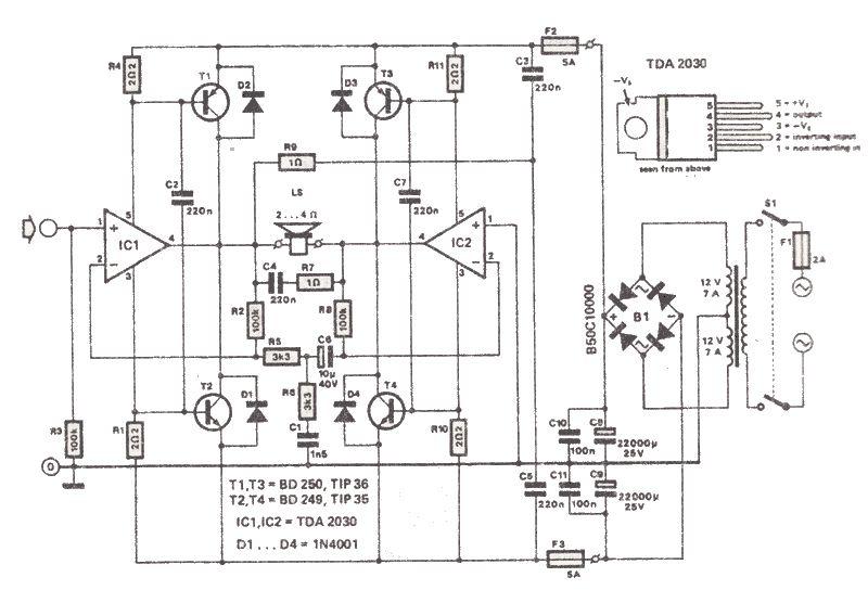
The TDA2030 is a low-cost audio power amplifier capable of delivering high output audio power up to 200 watts with a load impedance of 2 to 4 ohms. This high-power audio amplifier is built around the TDA2030 audio amplifier...
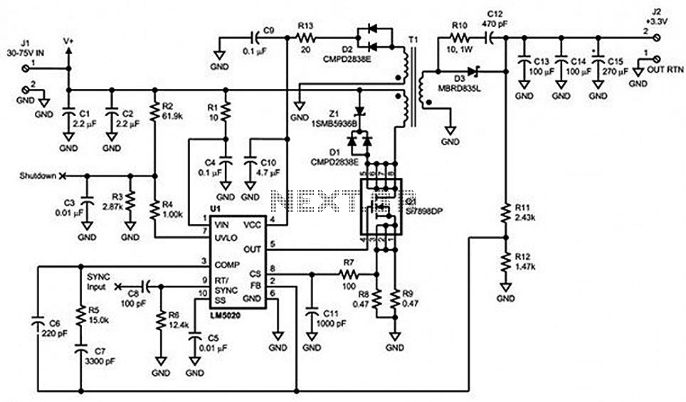
Locate sections such as the LM5020 connection diagram and pin descriptions, the functional block diagram of the device, the line under voltage lockout (UVLO) circuit, an internal high-gain error amplifier, a cycle-by-cycle overcurrent protection function, the setting of the...