
arduino Electret Microphone preamplification will it work for dynamic type microphone

The circuit operates as a basic analog signal processing system designed to interface with an Arduino microcontroller. The main components include a transistor for amplification and a voltage divider formed by resistors R2 and R4 to establish the necessary biasing for the ADC input. The design addresses the challenge of ensuring that the output signal remains within the acceptable range for the Arduino, which can only read positive voltages.
The voltage divider effectively shifts the signal level, allowing the ADC to interpret the full waveform, including both the positive and negative swings. This is crucial for applications that require accurate signal representation, particularly when dealing with AC signals. The choice of resistors R2 and R4 must be made carefully to achieve the desired bias point, which is typically set to half of the supply voltage (2.5V in this case) to maximize the signal swing.
The transistor's gain is managed by incorporating an emitter resistor with AC bypass, which stabilizes the gain and ensures that the output impedance is lower, making it more compatible with the ADC's input characteristics. The use of capacitors for coupling and bypassing can significantly affect the frequency response and transient behavior of the circuit. While larger capacitors may provide better low-frequency performance, smaller capacitors can also be utilized effectively, depending on the application requirements.
It is essential to consider the input impedance of the ADC when designing the circuit, as low input impedance can load the signal, leading to attenuation and inaccurate readings. The simulation parameters represented by Radc and Cadc help in understanding the interaction between the circuit and the ADC, guiding the design toward achieving optimal performance.
In summary, the circuit can be refined by experimenting with component values and configurations, such as exploring op-amp alternatives for improved sound quality. However, if the application can tolerate some distortion, the current design with appropriate biasing serves as a functional solution for interfacing with Arduino-based systems.The circuit is okay (not ideal for quality but it will work), but there`s one small issue if you want to feed the output to your Arduino. As shown, the output will swing below ground (i. e. it will be biased at 0V) and your Arduinos analog input will only accept positive voltages. The voltage divider is made from R2 and R4, and it biases (read "hol ds") the TO_ADC node at 2. 5V so the ADC pin sees the full swing of the signal. Without it the ADC would only see the positive half of the signal, because we have no negative power supply present. Then the output will be more like this (depending on your ADCs input impedance it may not work well though - this is the bit that is simulated by Radc and Cadc, I`ll check this shortly): Okay, here`s an option which controls the transistor gain properly (using the emitter resistor with AC bypass) and outputs a lower impedance signal that swings around ~2.
5V (V+ is 5V - the capacitors do not have to be as large as 10uF, you can still use 100nF if you wish for your input capacitor): Radc and Cadc are not components you need to add (so you can ignore them if/when you make the circuit), they represent your microcontrollers analogue input pin characteristics. Some microcontroller ADCs can have quite low input impedances which can load your signal and attenuate it (so basically you end up with a lower reading than you expected) We can see this handles a 20mV input pretty well, if we input 20mV to the original circuit (even without any loading), we get some distortion due to the uneven gain (note flattened edges on negative swing): There are still better options and variations (the above may need the values tweaking a little) A simple opamp circuit would be one, but it depends on how concerned you are about the sound quality whether you would want to bother.
If you`re happy with a bit of distortion, then the first circuit with a suitable method of biasing will be fine. 🔗 External reference
Related Circuits
This system consists of two opto-isolated circuits that facilitate data transmission via an infrared network device between two computers. For instance, a user can transfer files from a desktop computer to a laptop computer without the use of cables,...
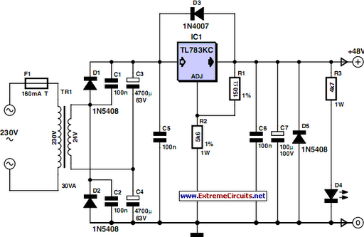
48 V phantom powering has become the standard for professional condenser microphones. The supply voltage is applied over both wires of the balanced screened cable via two 6.8 kΩ resistors. The absolute value is not critical, as a variation...
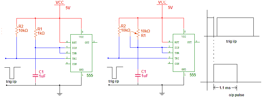
A project involving a circuit utilizing the IC555. The IC555 is a highly versatile integrated circuit that can be employed in nearly every type of application due to its multifunctionality. As it is a built-in multivibrator, the IC555 allows...
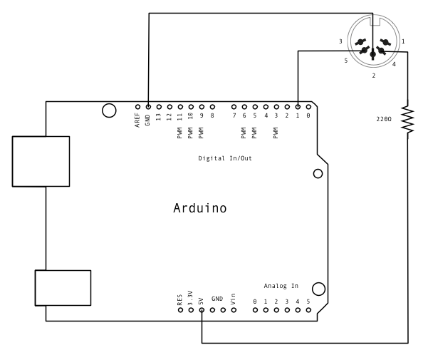
MIDI, or Musical Instrument Digital Interface, is a protocol designed for controlling synthesizers, sequencers, and various musical devices. MIDI devices are typically categorized into two main classes: controllers, which generate MIDI signals based on user input, and synthesizers, which...
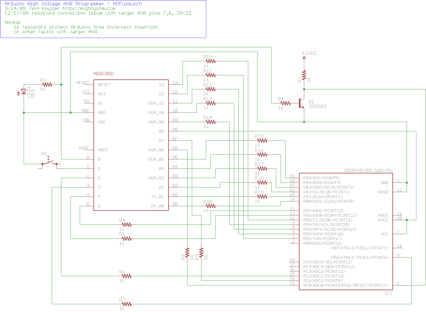
The project explains how to create a simple AVR High Voltage Programmer using Arduino. It can be utilized to fix or recover incorrectly fused AVR chips. The AVR High Voltage Programmer is designed to reprogram AVR microcontrollers that have been...
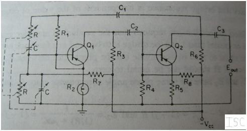
This article explains the construction and working of feedback oscillators, with a detailed description of the Wien bridge oscillator and phase shift oscillator, along with their circuit diagrams, basic components, and practical applications. Oscillators are electronic devices that produce...