
Types of feedback oscillators

The Wien bridge oscillator is a popular feedback oscillator known for its simplicity and effectiveness in generating sinusoidal waveforms. The basic configuration includes a combination of resistors and capacitors arranged in a bridge circuit, with an operational amplifier providing the necessary gain. The Wien bridge employs a specific arrangement of resistors (R1, R2) and capacitors (C1, C2) to establish a feedback loop that maintains oscillation. The balance condition of the bridge, achieved when the gain of the amplifier equals the attenuation of the feedback network, is crucial for sustained oscillation.
The frequency of oscillation (f) can be calculated using the formula:
\[ f = \frac{1}{2\pi R C} \]
where R is the resistance and C is the capacitance in the feedback loop. The operational amplifier must have a gain that compensates for any losses in the bridge circuit to ensure that the overall gain is greater than one. The phase shift introduced by the RC network is vital, as it allows the feedback to reinforce the input signal at the desired frequency, thus generating a stable sinusoidal output.
In practical applications, the Wien bridge oscillator is widely used in audio frequency generation, signal processing, and testing equipment, owing to its ability to produce clean and stable waveforms. The phase shift oscillator, on the other hand, utilizes multiple RC stages to achieve a total phase shift of 360 degrees, allowing for oscillation at lower frequencies. Both oscillators demonstrate the essential principles of feedback and phase relationships in electronic circuit design, making them fundamental components in various electronic systems.This article explains the construction and working of feedback oscillators with detailed description of Wien`s bridge oscillator and phase shift oscillator along with their circuit diagram, basic components and practical application Oscillators are those electronic devices that produce a sinusoidal wave form at their output upon application of dc voltage at their input terminals. Although other types of wave forms can also be obtained from them but the basis wave form that they produce is sinusoidal. There can be different types of oscillators like feedback oscillator and negative feedback oscillator.
Here we will be see how we can classify feedback oscillator along with their working principle. These are the oscillators that involve resistor and capacitor in their circuitry for the purpose of required feedback to the amplifier. These categories can further be classified in to two types that are given as: It is so important type of feedback circuit that it provides a standard as the variable frequency testing circuit in audio frequency range.
The operation of this circuit is very simple. Also it is less complex than LC oscillators. It is actually an audio oscillator that is used in the frequency range of audible range generally generated through speakers. And it is seldom used in testing of those electronic circuits that operate upon audio frequencies. Usually a sinusoidal wave form is generated by this type of oscillator that occurs to be variable both in frequency and amplitude so that it may be adjusted according to the concerned application.
Other than sinusoidal waveform some other wave forms can also be generated with help of them like square wave but it utilizes the same principle for that purpose too. The amplitude generated by them is generally in the range of about 25V and frequency occurs in range of about 20Hz to 20 KHz.
The output impedance of the audio oscillator is in the range of 75 to 600 ohm. The most common oscillators as Wien`s bridge oscillator and phase shift oscillator and both of them apply RC network in their operation. There are some very important features regarding RC oscillators are: It is actually a type of feedback oscillator where the function of the Wien`s bridge is to provide inversion of phase.
There inversion of phase does not mean to shift the phase by 180 degree only but the shift in phase can be by any angle. It is basically an AC bridge such the balance is achieves at the particular frequency of the whole frequency under given range.
Here is a circuit diagram that shows the circuitry set of a Wien`s bridge network. There are capacitors, resistors and an operational amplifier represented by a triangular symbol getting input from the net work formed by passive components. There are some conditions for oscillations to occur one of them is that he phase shift between E1 and E2 should be equal to zero which is possible in one situation when the bridge is made to be balanced.
The frequency of oscillations is given by: Second condition for making oscillations to occur is the product of gain constant of amplifier and constant H should come to be greater than unity. The requirement of the bridge is to provide feedback to the operational amplifier so the value of E2 should remain always greater than one and phase shift between the two i.
e. E1 and E2 remain to be zero. From the discussion so far it has become clear that frequency of oscillation `s` is equal to that of resonance. And Ea does not come to be equal to E1 at any frequency other than resonance frequency. This results in the consequence that the difference of Ea and Eb does come to be in phase with E1. The capacitor that is used in above circuit is of air by variable capacitor which is mounted on the same shaft.
The change is frequency of the bridge is done by means of this capacitor. But this leads to only small variations in frequency while for large variations there exit 🔗 External reference
Related Circuits
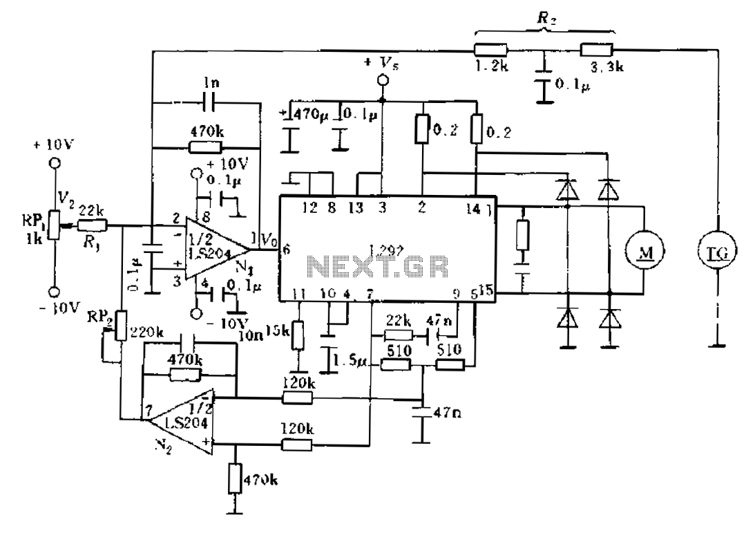
An alternative solution involves enhancing the existing feedback signal directed to an error amplifier summing junction, which is integrated into a current feedback loop for improvement. The L292 circuit demonstrates that the electrical current is proportional to the average...
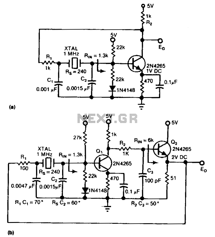
The circuit is an inverter configured as a linear amplifier. By incorporating a crystal and capacitors into the feedback path, the amplifier is transformed into an oscillator, enabling it to oscillate at or near the crystal's resonant frequency. Trimmer...
One application of this handy circuit is a graphic equalizer, created by feeding a signal to a number of parallel band-pass filters each tuned to a different frequency; typically octaves apart. Then, you can adjust the strength in each...
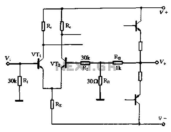
The circuit utilizes the configuration illustrated in Figure 1-36, with the feedback circuit and bias circuit implemented separately. The feedback resistor, Rfl, is approximately 30 ohms. To maintain the desired amplification, the resistor R queue is set to 1...
These filters are useful for equalisation, analysis and other tasks such as the Sound to Light converter (Project 62) or even a fully functional Vocoder. For those who have not heard of the vocoder, it is a device that...
A basic Wien Bridge Oscillator utilizes a filament lamp in conjunction with an operational amplifier (op-amp). The property of filament lamps, specifically the non-linear increase in resistance of the tungsten filament as it heats, plays a crucial role in...