
RJ45 Network card to IR communication

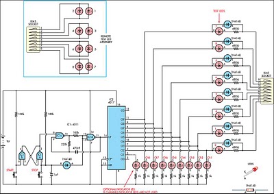
This system employs two opto-isolated circuits to enable wireless data transfer between computers through infrared technology. The use of infrared diodes allows for a cable-free connection, streamlining the file transfer process. The connection to the 10/100 Mbps network cards requires careful preparation of a very short network cable, ensuring that one end is stripped for proper wiring.
In terms of connections, the Tx+ output from one network card must be linked to the Rx+ input of the opposing card, and similarly, the Tx- must connect to the Rx- of the other card. This configuration is crucial for maintaining the integrity of the data transmission. The power supply setup is also critical; utilizing a 9V battery in conjunction with the +5V output from the desktop's power supply ensures that the circuits function effectively. It is essential to ground the power supply to the circuit ground to avoid potential issues with signal integrity.
For the laptop, a combination of a 9V battery and a 4.5V battery is recommended, providing the necessary voltage levels for the opto-isolated circuits. The requirement for the use of 74H series digital components is significant, as these components are designed for rapid response times, which is vital for maintaining efficient data transfer rates. Proper grounding of all GND pins and correct Vcc connections for each logic integrated circuit is necessary to ensure reliable operation of the system.
Overall, this schematic enables a straightforward yet effective method for wirelessly transmitting data between computers, leveraging the advantages of infrared technology and careful circuit design.This system, composed of two opto-insulated circuits, allows the data transmission per infra-red network device between two computers. For example, someone can transfer his files starting from his desktop computer to his laptop computer without using any cable.
How By using infra-red diodes. We have to connect a circuit to the 10/100 Mbps network card of both computers by using a very small network cable (can be smaller than 10 cm). One of the two extremities of the cable must be removed to allow the wire connections. We must pay attention when we do the connections. The Tx+ output of any network card is connected to the input of the Rx+ of the other with the cable. It`s the same way for the Tx- and the Rx-. We have to supply the circuits with two sources of voltage. I recommend to use a 9V battery and the +5V output of the power supply for the desktop computer. The ground of the power supply must be connected to the ground of the circuit. For the laptop computer, I recommend to use a 9V battery and the 4. 5V battery. All digital components must be of the 74H series because these have short response times (less than 2. 5 ns). All the GND pins of the logic integrated circuits must be connected to the ground of their circuit and their Vcc pin must be connected to the +Vcc of their circuit.
🔗 External reference
Related Circuits
This circuit was developed to create a simple network tester that can be operated by a single individual. Commercial units typically require a second person to monitor the remote LEDs, as the transmitters lack the ability to continuously cycle...
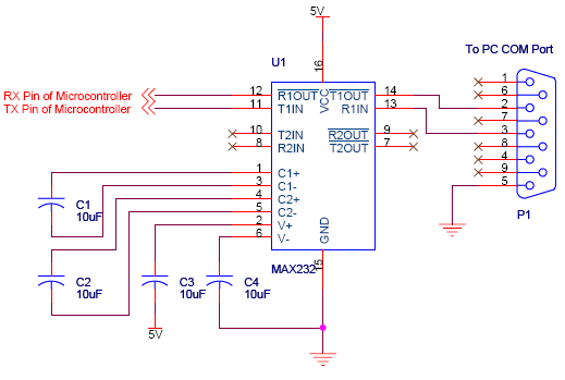
Serial communication using UART or USART of a microcontroller 8051 AVR PIC, software implementation of half-duplex UART and MAX232 interfacing with microcontrollers 8051 AVR PIC. The described system focuses on implementing serial communication via UART (Universal Asynchronous Receiver-Transmitter) or USART...
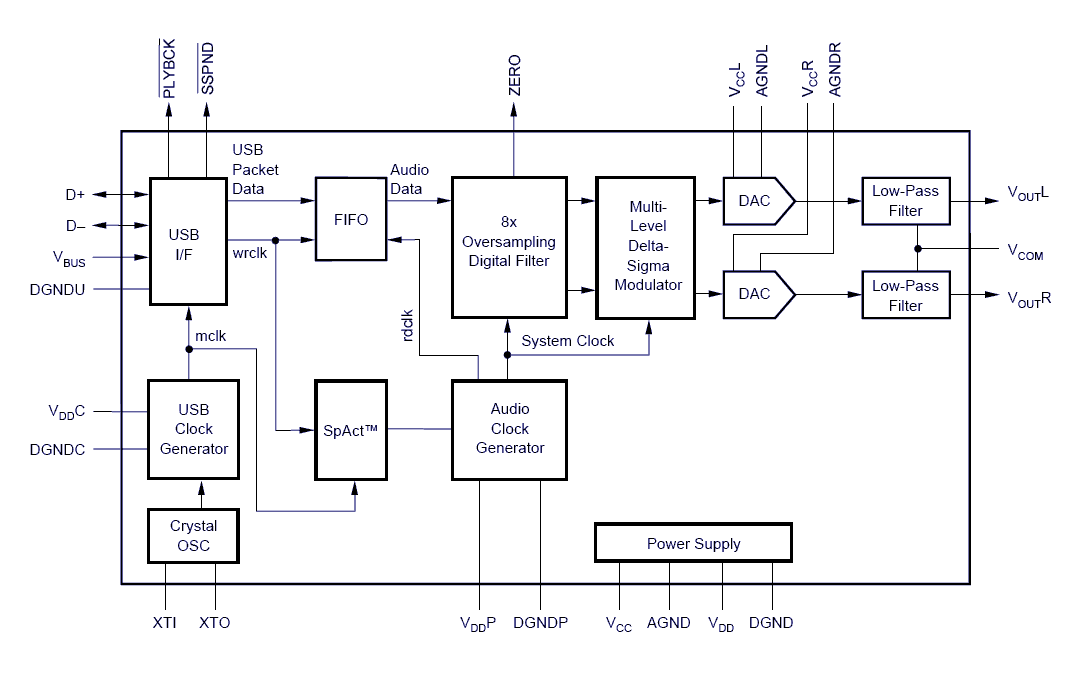
Designing and building a USB sound card is no longer a headache with the PCM2702 integrated circuit from Texas Instruments. The PCM2702 is a digital-to-analog converter (DAC) that features digital-to-analog output channels. The integrated interface controller of the PCM2702...
As shown in the figure, D187 is a UART with its RX/TX signals connected through optocouplers N21, N22, and N29, providing complete optoelectronic isolation for the RS-485 communication interface receiver/transmitter D28 and microprocessor D211. D197 serves as a generator,...
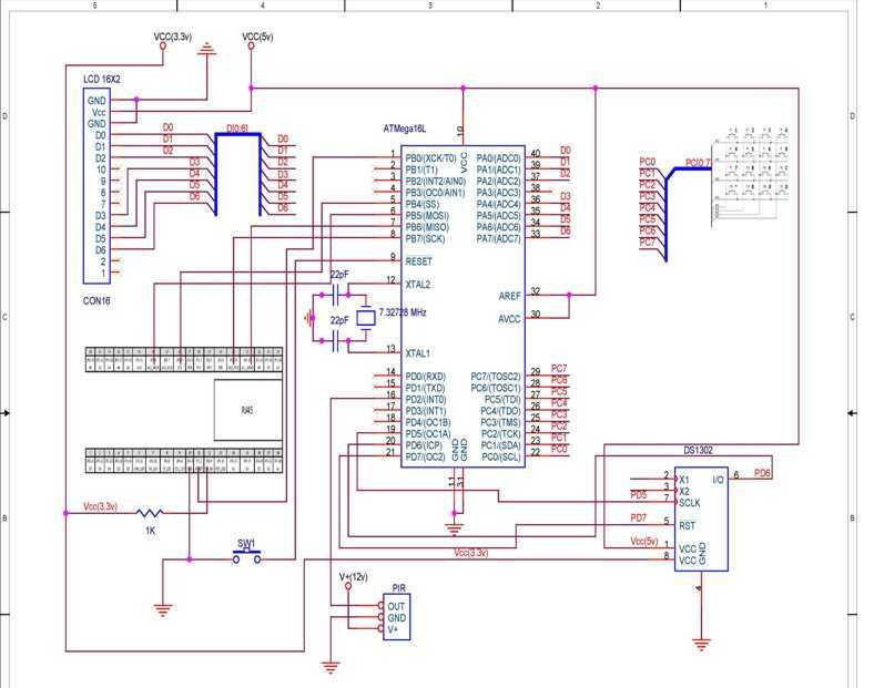
TCP based security system using the Ethernet module offered within the contest, an ATmega16L microcontroller, a PIR as a sensor and few other peripheral devices, which is specially targeted for homes and small business owners. I have used through...
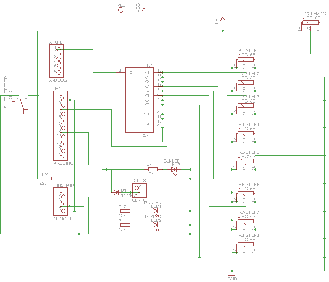
A custom Lo-fi Arduino Guitar Pedal has been developed, utilizing a repurposed enclosure and twisted pair converters. Currently, it features a single output, with potential for future expansion. The design includes a digital delay effect, which was initially intended...