
arduino electronics
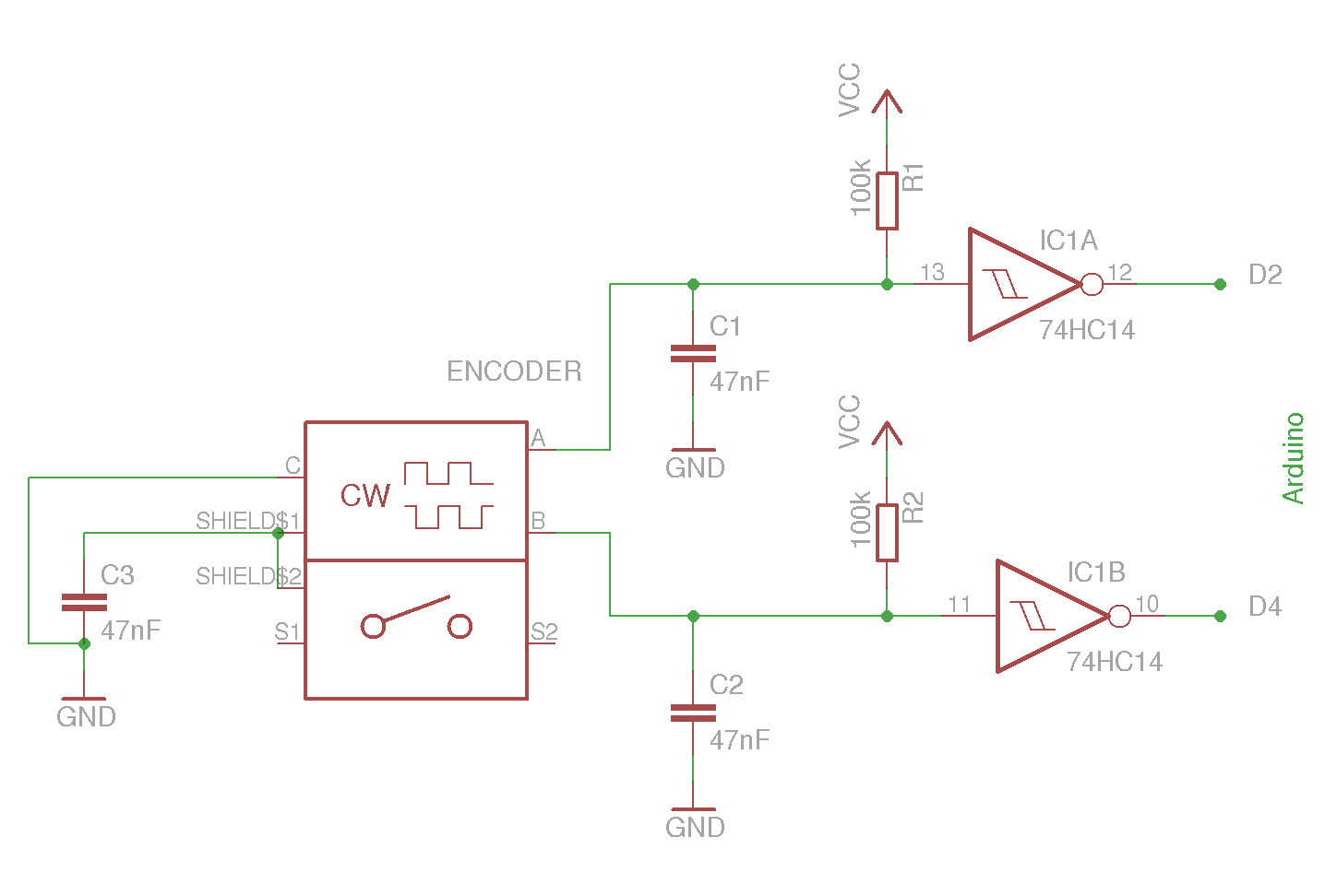
The rotary encoder circuit utilizes an electromechanical device that converts mechanical rotation into electrical signals. The encoder typically features two output pins (A and B) that provide quadrature outputs, allowing for the detection of both direction and speed. The encoder's functionality is based on the principle of detecting changes in the output states, which can be processed using an interrupt-driven approach to minimize latency and ensure accurate readings.
In the described application, the encoder is connected to an Arduino microcontroller, specifically the ATmega328P, which is programmed to monitor the state of the encoder pins. The setup function initializes the pins as inputs and configures interrupts to trigger on either the rising edge or on any change, depending on the encoder's characteristics. The loop function continuously outputs the current value of the encoder, providing real-time feedback on its position.
To enhance signal integrity, debouncing techniques are implemented using hardware components. The use of 47nF ceramic capacitors in conjunction with Schmitt triggers helps filter out noise and contact bounce that might occur during rapid rotations. This hardware approach ensures that the signals received from the encoder are clean and reliable, allowing for precise control over the motor that operates the door.
The motor control mechanism is straightforward, relying on a simple circuit closure to initiate movement. A brief pulse sent through the control lines will toggle the motor's state, opening or closing the door as required. The design considers operational safety, ensuring that the motor can reverse direction if it is already in motion when a new command is received.
For wireless communication, the integration of 433MHz ASK modulated RX/TX modules provides a cost-effective solution for remote control operations. The VirtualWire library simplifies the interfacing process, allowing for the transmission and reception of commands over a distance. Despite the limitation of one-way communication, efforts are made to secure the data being transmitted, utilizing methods to obfuscate commands to prevent unauthorized access.
Overall, this schematic integrates various electronic components and programming techniques to create a functional and secure rotary encoder and motor control system, suitable for applications requiring precise positional feedback and wireless control.The example circuit and the code should be enough to get you started if you don`t want to read the other mumbo jumbo. A rotary encoder is electromechanical component with a shaft. Shaft rotation is recorded and converted to electrical pulses that tell in which directionthe shaft is rotating.
The shaft has unlimited 360 degree rotation. If we can detect that the pins are changing we know that the shaft is rotating. How often the pulses change tells us how fast it`s turning. How many times it has changed tells us how far it has been turned etc. Your datasheet will reveal which type you have. There will be a pulse diagram in of the pulses at clockwise operation that looks something like one of the below pictures. The dotted lines indicate shaft stops. Cheap encoders are known to cause a lot of contact bounce so you will need to debounce the signal from the encoders.
We will use interrupts on the Arduino for detecting encoder rotation so it`s easier to debounce the encoder with hardware and get nice clean pulses than to try and debounce using software delay. I have tried some variants and settled with 47nF ceramic capacitors and Schmitt Triggers on the outputs.
I have also connected the shield on my encoders to ground through another 47nF ceramic capacitor. If you have an encoder that stops at both closed and open you will have to turn your encoder two clicks to register a turn. Correct this by changing the interrupt type from RISING to CHANGE sol that an interrupt is triggered on every change.
int pinA = 2; //Encoder pin A connects to interrupt 0 (D2) int pinB = 4; //Encoder pin B connects to D4 int iValue = 0; //A variable that will be increased or decreased //when we turn the encoder void setup() { Serial. begin(9600); pinMode(pinA, INPUT); pinMode(pinB, INPUT); // Enable interrupt on encoder pin A // Trigger at RISING if your encoder stops (clicks) only at high pulse // Trigger at CHANGE if your encoder stops (clicks) at both high and low // positions or if it has no stops attachInterrupt(0, encoderClick, RISING); } void loop() { // continuously print the value to see how it changes Serial.
println(iValue); delay(200); } void encoderClick(){ // encoder must have turned one click because interrupt 0 was triggered // read value from both encoder pins int valA = digitalRead(pinA); int valB = digitalRead(pinB); // compare pins to determine in which direction encoder was turned if (valA != valB){ // pinA just changed but pinB had not yet changed // Direction must be clockwise if A changes before B iValue+; } else{ // pinA just changed and pinB had already done so. // Direction must be counter-clockwise if B changes before A iValue-; } } The motor to the door is controlled by shorting two cables and thereby closing a circuit.
A short pulse is enough to start the motor. If the door is closed it will open. If it`s already open, the door will close. If the motor is moving when the pulse arrives it will change direction. I wanted a new solution that would be a bit more secure and hopefully have the same range as the old one had and I wanted to base it onan ATmega328P with an Arduino core and some really cheap 433Mhz ASK modulated RX/TX modules that can be found everywhere on eBay. I have used these RF modules before and know they have a decent range and can penetrate doors, windows and even walls in some cases.
They are also easy to interface with using the VirtualWire library for Arduino. The downside is that they only work in one direction. Even if it wasn`t really necessary in this case I wanted to implement some kind of security or obfuscation of the commands sent over the air. This is something of a challenge with a system that only communicates in one direction since it`s not possible to use a challenge/response based protocol and the Arduino doesn`t have storage enough to store predefined
🔗 External reference
Related Circuits

This Arduino-powered vocal effects box pitch shifts and distorts incoming audio signals to produce a wide variety of vocal effects. This project is an experiment with real-time digital signal processing using Arduino. It samples an incoming microphone signal at...
A flip-flop is a bistable multivibrator. It is a circuit that has two output states and is switched from one to the other by means of input signals. A flip-flop serves as a fundamental building block in digital electronics, primarily...
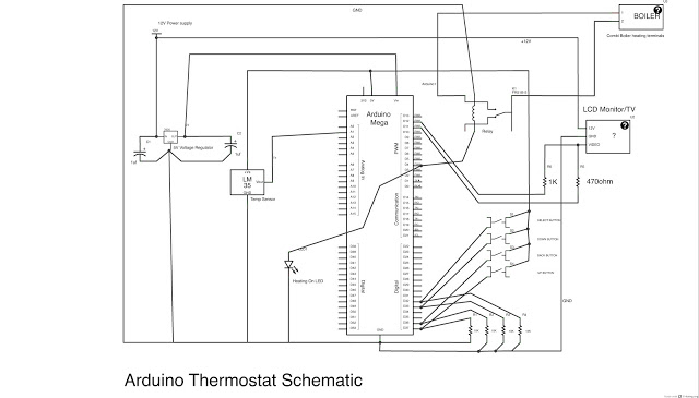
This post outlines the steps taken to build an Arduino-based thermostat, as demonstrated in accompanying videos. The first video showcases a preliminary version of the menu system, providing an overview of the features. The second video presents the completed...
The approximate center of the base was marked, and a hole was drilled large enough to accommodate a setscrew for the servo armature. The armature was then secured to the underside of the base using hot glue, ensuring that...
Yesterday, a decision was made to abandon watching a movie in favor of building a binary clock. After some contemplation on the programming aspect, the project was successfully completed. The clock operates effectively, and a detailed explanation of the...
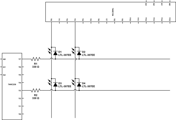
To construct a 7 to 128 demultiplexer using 3-to-8 and 4-to-16 demultiplexers, the three highest bits of the output address should be fed into the 3-to-8 demultiplexer. The outputs from this demultiplexer will serve as the enable inputs for...
Warning: include(partials/cookie-banner.php): Failed to open stream: Permission denied in /var/www/html/nextgr/view-circuit.php on line 713
Warning: include(): Failed opening 'partials/cookie-banner.php' for inclusion (include_path='.:/usr/share/php') in /var/www/html/nextgr/view-circuit.php on line 713