
led Arduino multiplexing help needed
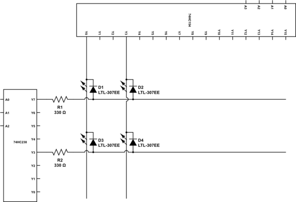
In a simulation setup using CDS, a 74LS138 is utilized as the 3-to-8 demultiplexer, with seven 74HC154 devices functioning as the 4-to-16 demultiplexers. The address outputs from an Arduino are represented by SPDT switches, with one terminal connected to Vcc and the other to digital ground. Issues have arisen where the LEDs do not illuminate, likely due to incorrect connections involving the enables. The anodes of the LEDs are soldered together, while the cathodes must connect to the outputs of the 4-to-16 demultiplexers, indicating a potential misunderstanding regarding the enable signals.
The circuit design involves a hierarchical arrangement of demultiplexers to achieve the desired output range. The 3-to-8 demultiplexer (74LS138) will decode the three most significant bits (MSBs) of the address input, generating eight outputs. Each output corresponds to one of the enable inputs of the 4-to-16 demultiplexers (74HC154). Each of these demultiplexers can handle four bits of input, allowing for a total of 16 outputs per device.
The enable pins of the 4-to-16 demultiplexers must be appropriately controlled by the outputs from the 3-to-8 demultiplexer to ensure that only one 4-to-16 demultiplexer is active at any given time. This multiplexing scheme allows for the selection of one out of 128 possible outputs based on the combination of the three MSBs and the four least significant bits (LSBs) fed into the selected 4-to-16 demultiplexer.
It is crucial to verify that the output current ratings of the demultiplexers are sufficient for the intended application. If the current capacity is inadequate for driving the LEDs directly, a transistor can be employed as a switch to amplify the current from the demultiplexer outputs to the LEDs, ensuring reliable operation. Additionally, attention should be paid to the polarity of the enable signals; inverters may be necessary if the enable logic levels do not match the requirements of the demultiplexers.
In summary, this demultiplexer configuration enables a flexible and efficient method for controlling multiple outputs, making it suitable for various electronic applications where multiple signals need to be managed effectively. Proper attention to the design and connections will facilitate the successful implementation of the circuit.If you want to build a 7 to 128 demux with 3-to-8 and 4-to-16 demuxes, then put the 3 high bits of your output address into the 3-to-8, and use the outputs of that as the input enable to the individual 4-to-16 demuxes (assuming that it has an enable pin), so the output #0 on the 3-to-8 would go to the input enable of the first4-to-16 demux, the output #1 would go to the second, etc. No other components I can think of, except possibly inverters if the input enable is the wrong polarity. Also check that your demux can source enough current to power the LED, if not then you may need to use a transistor to boost the current.
@SamuelPogue Tim May 2 `13 at 23:43 I am attempting to simulate this using CDS using a 74LS138 as the 3-to-8, and 7 74HC154`s for the 4-to-16`s. I have it set to where SPDT`s represent the address outputs on the arduino where one lead is connected to Vcc, and the other is connected to digital ground.
However something is going wrong here and the LED`s won`t light. Because I have all the anodes of the LED`s soldered together, and the cathodes have to be the ones to connect to the outputs of the 4-to-16`s, I am assuming I am doing something wrong with the Enables. Of course, I am trying to discern why there are multiple Enables. Samuel Pogue May 3 `13 at 20:42 🔗 External reference
Related Circuits
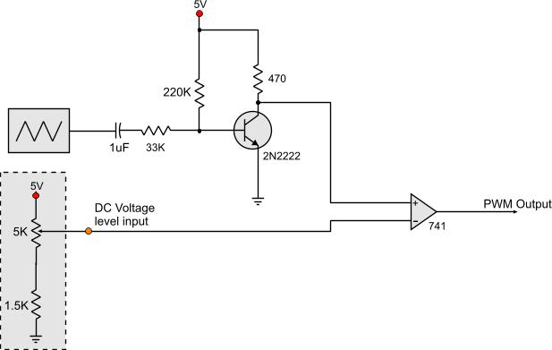
Circuits that generate PWM pulses typically translate a resistor value into a change in duty cycle. While this method is convenient, there are instances where a voltage-controlled PWM generator is required. Although microcontrollers can produce a variety of PWM...
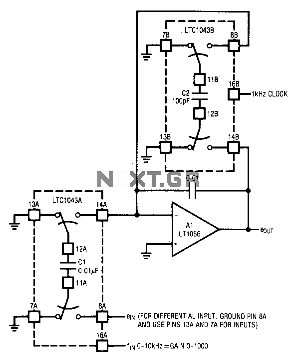
The circuit utilizes the LTC1043 in a variable gain amplifier configuration, which offers continuously adjustable gain, gain stability of 20 ppm/°C, and supports both single-ended and differential inputs. Two separate LTC1043 devices are employed in the design. The LTC1043B...
Watching the time on a mobile phone in the dark can cause discomfort due to the strong contrast between bright and dark backlighting. To address this issue, the "ICON" model is utilized, which operates in standby mode with a...
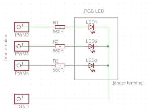
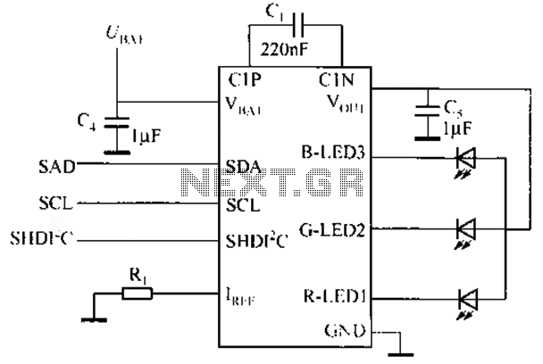
This evening, after returning home from a paragliding appointment, there was a realization that the RGB LED driver code written the previous day needed improvement. The code was refined and annotated extensively for educational purposes. Although the current skill...
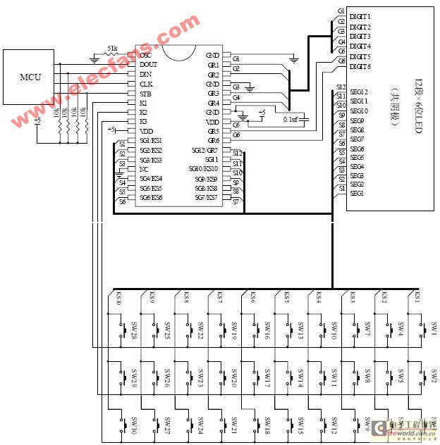
The ET6201 is a LED display control drive circuit with a duty cycle of 1/7 to 1/8. It features 11 segment output gates and 1 segment/gate output, along with a display memory, control circuit, and key scanning circuit, which...
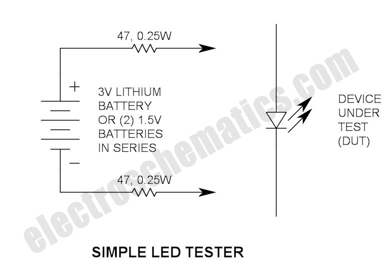
Do not let its extreme simplicity deceive you — this device is useful! Many have been made over the years, and some have even been given away as gifts. Yes, multimeter... A multimeter is an essential instrument in electronics, used...