
arduino freertos fan rpm video

The circuit design for this Arduino-based fan speed measurement system incorporates several critical elements that facilitate effective operation. At its core, the Arduino microcontroller serves as the processing unit, interfacing with an IR sensor to detect the passage of fan blades. The IR sensor is connected to a digital input pin on the Arduino, configured to trigger an interrupt on the falling edge of the signal. This interrupt service routine (ISR) is essential for accurately counting the number of rotations per minute (RPM) by registering each blade that passes the sensor.
To enhance functionality, a thermistor is included in the circuit to monitor the temperature of the environment or the fan itself, providing valuable feedback for potential adjustments in fan speed based on temperature readings. The PWM speed controller, implemented through an opto-coupler, allows for control of the fan speed by modulating the voltage supplied to the fan, effectively adjusting its operational speed based on the calculated RPM.
The choice of components is critical for the performance of the circuit. The CNY 75B opto-coupler is selected for its ability to handle the voltage levels involved, while the biasing resistors ensure that the IR transistor operates in the appropriate mode. The combination of the 100K ohm resistor for the IR transistor and the series resistors for the IR LED is designed to optimize switching performance, minimizing response time and maximizing accuracy in speed measurement.
The software architecture built on FreeRTOS allows for multitasking capabilities, with each task performing specific operations such as reading the IR sensor, updating the RPM calculation, and controlling the fan speed. This structured approach not only enhances the efficiency of the system but also provides a framework for future expansions or modifications, such as adding additional sensors or integrating more complex control algorithms.
In summary, this Arduino-based project effectively combines hardware and software elements to create a robust system for measuring and controlling the speed of a computer fan, demonstrating the principles of embedded systems design and the integration of electronic components for practical applications.An Arduino measuring the rotational speed of a basic computer fan. It was one of a number of YouTube videos I did as I was studying for a Masters in Computer Science. This particular module was an embedded systems programming course, with a bit of electronics thrown in. Here`s the video: I was recently asked if the schematics were available for this video. Unfortunately I was unable to locate the schematics as shown in the video, however I do have the source code. This is a simple Arduino Sketch that uses an open source Timer` library. You can download the fan-rpm-sketch source code. When reading this source code please keeping in mind that there are three processes going on: b) IR ISR this interrupt routine is configured to be triggered by the falling edge of the IR input i. e. whenever the leading (or falling, I forget which) fan blade edge passes the sensor c) A Timer routine that is attached to a high speed timer and called every second to calculate the RPM value extrapolated from the number of fins seen that second.
The difference between the two is the addition of two modules to the layout the thermistor temperature sensor, and the opto-isolated pulse-width-modulated speed controller. On the software side, we now use FreeRTOS on Arduino. The use of an opto-coupler is separates the low voltage Arduino digital IO from the slightly higher voltage used to power the Arduino board and the Fan.
Potentially any voltage is supported up to the limits of the CNY 75B part. The IR transistor from radio shack required a large bias resistance to place it in switching` mode rather than amplification mode. A 100K ohm resistor was chosen. An approximate 100 ohm current limiting resistance for the IR LED was provided through two 47ohm resistors in serial.
Using the 12V fan in conjunction with a 7. 5V power source is not optimal but it works. The current required to feed the base of the NPN transistor is obviously changed by the lowered voltage, so the resistances used needed to be different. A 4. 7k ohm resistor was placed in parallel with a 10k ohm resistor which appears to provide a faster response from the fan ( I assume due to lowered switch time of the NPN transistor ).
The system software is built upon FreeRTOS but is wrapped in a C+ layer. All tasks inherit from a task class that provides wrappers around functions applicable to tasks, including creation, stack and priority configuration, and the ability to invoke a derived (virtual) method that is the actual task code provided by the implementor of the derived class. In addition to tasks, there is one other class to wrap the configuration of timer 2 as a PWM output. The combination of timer 2 and output compare B means that we are driving pin 3 as the PWM output. However, it needed to implement a global override of the new operator to call pvPortMalloc the FreeRTOS implementation.
In addition I had to place dummy overrides for pure virtual and guard C+ runtime implementation functions. The original setup method is used to both initialize all tasks in the system configure the hardware to some base state, and then invoke the FreeRTOS Scheduler.
If something goes wrong, it falls through to the original arduino sketch loop method, which is implemented to provide a distinct LED pattern so that this error condition can be seen. After implementing the C+ layer, however, it became readily apparent that something was wrong, as the stability of the software was variable depending on the order in which tasks were created, whether they were created in FreeRTOS.
What is provided is a working version, but only after much trial and error. Changes to stack sizes, queue sizes, serial debug messages, adding of tasks, or changing the order of tasks and hardware initialization is not recommended! I suspect but cannot be sure that the combination of heap, stack, and static allocations c 🔗 External reference
Related Circuits
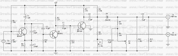
This intermediate frequency (IF) system employs a NE602 oscillator/mixer to convert VHF television signals ranging from 60 to 72 MHz (channel 13 or channel 4 under the U.S. NTSC standard) down to 45 MHz. A surface acoustic wave (SAW)...

The automatic fan controller circuit depicted in the schematic features two comparators with distinct triggering points that can be adjusted independently. LM135 or... The automatic fan controller circuit is designed to regulate fan operation based on temperature variations. It employs...
This circuit is a RF modulator which can be used for modulating of video signals. The P1 controls the Light and the P2 controls the contrast of video signal. The RF modulated output signal can be received on the...
This page outlines the development of electronics for displaying a monochrome video image on an electrostatic oscilloscope tube. This work complements the Electron Optics section in the Experiments category. The primary objective is to showcase a moving video image...
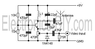
This is a simple video transmitter capable of transmitting signals up to 50 meters. It can be utilized with cameras or other video sources and allows viewing on VHF channel analog televisions. The video transmitter operates on a supply...
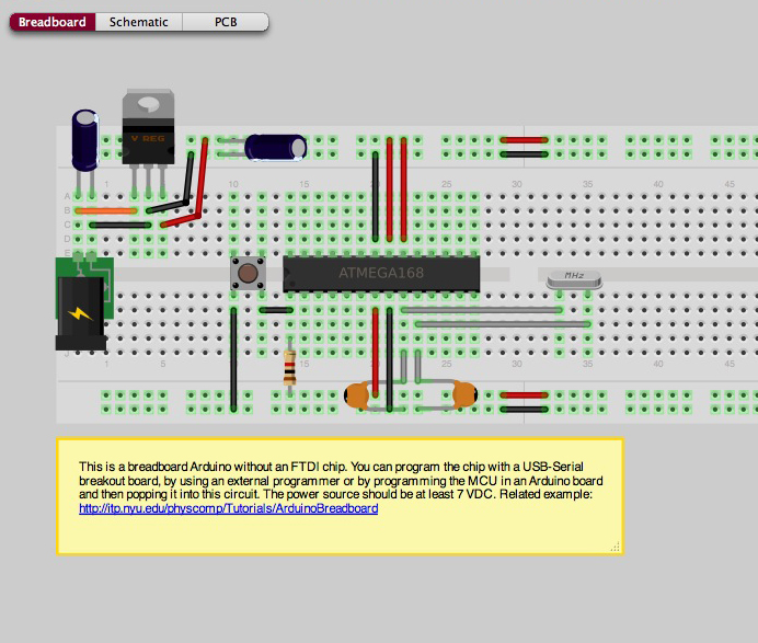
It is possible to construct a basic Arduino setup independently. This project illustrates a breadboarded Arduino configuration that does not utilize an FTDI chip, which implies the absence of USB connectivity. However, USB connectivity can be achieved through the...