
Automatic Fan Controller Circuit

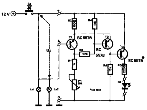
The automatic fan controller circuit is designed to regulate fan operation based on temperature variations. It employs two comparators, typically operational amplifiers configured as comparators, which monitor the temperature through a temperature sensor, such as an LM135 or a thermistor. The circuit allows for individual adjustment of the triggering points for each comparator, enabling customization of the activation and deactivation thresholds for the fan.
In this configuration, the first comparator is set to activate the fan when the temperature exceeds a predetermined level, while the second comparator can be set to deactivate the fan when the temperature drops below a different threshold. This dual-threshold system ensures efficient cooling and prevents unnecessary fan operation, contributing to energy savings and extended component lifespan.
The LM135 can be used as a temperature sensor, providing a voltage output proportional to the temperature. The output of the LM135 is fed into the inverting and non-inverting inputs of the comparators. By adjusting the reference voltages applied to the non-inverting inputs, the triggering points can be finely tuned to meet specific cooling requirements.
The circuit may also include additional components such as resistors, capacitors, and possibly a relay or transistor to drive the fan. The relay or transistor acts as a switch that controls the power supplied to the fan based on the output of the comparators. This arrangement allows for a robust and efficient fan control system, suitable for various applications where temperature regulation is essential.
Overall, the automatic fan controller circuit offers an effective solution for managing fan speed and operation based on ambient temperature conditions, promoting optimal performance and energy efficiency.The automatic fan controller circuit shown in the schematic has 2 comparators with different triggering points that are independently adjustable. LM135 or.. 🔗 External reference
Related Circuits
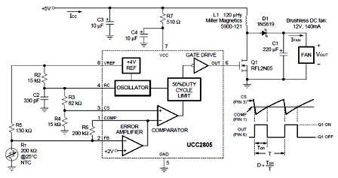
A temperature-controlled pulse-width-modulator (PWM) boost converter circuit diagram is illustrated in the following figure. This boost converter is designed to operate a 12V fan using a 5V supply while maintaining temperature control. The temperature-controlled PWM boost converter circuit operates by...
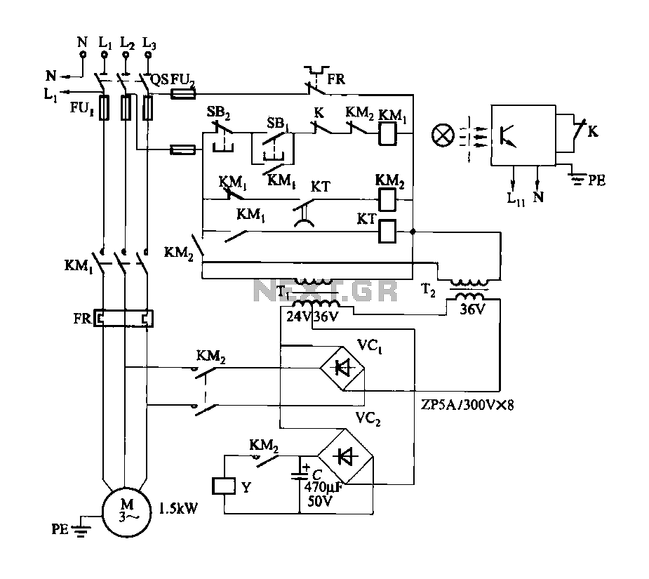
Figure 3-142 illustrates the reel control circuit. The coiler is utilized for winding plastic banding, such as grafting tape, onto a plastic reel. To prevent the plastic tape from being pulled off due to its low tensile strength, the...
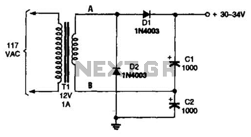
The voltage doubler consists of two diodes (D1 and D2) and two capacitors (C1 and C2), which are supplied by a 12-V, 1-A step-down transformer (T1). The voltage doubler circuit is designed to convert a lower input voltage into a...
This circuit addresses the issue of phone line interruptions caused by simultaneous use of a modem or fax machine when another phone is picked up. It indicates the status of the phone line by illuminating a red LED when...
The circuit described below monitors the car's brake lights and indicates their operational status using a 12V light-emitting diode (LED). This functionality can prevent fines for driving with defective brake lights and enhance road safety. The monitor relies on...
The Zero Volt Diode (ZVD) is a circuit useful in various applications, including solar chargers of all types. It is a novel circuit where a power MOSFET functions as a very low voltage drop diode, switching states at 0V...