
Arduino GSM Shield
The Arduino GSM Shield is a versatile module designed to enhance the functionality of Arduino-based projects by enabling cellular communication capabilities. The integration of the Quectel M10 radio modem provides robust connectivity options, allowing developers to create a wide range of applications that require internet access, SMS capabilities, and voice communication. The shield's architecture is optimized for ease of use, with clear pin assignments for software serial communication, ensuring that integration with the Arduino platform is straightforward.
In terms of power requirements, the GSM Shield is designed to operate efficiently under varying loads, with peak current consumption reaching up to 2A during data transmission. This necessitates the use of an external power supply to ensure reliable operation, particularly in applications where high data throughput is expected. The large capacitor incorporated into the shield serves to smooth out power fluctuations, maintaining stable operation during peak demand.
The audio interfaces provided by the shield facilitate the integration of both microphone and speaker components, enabling users to build interactive voice applications. The capability to handle both analog input and output opens up possibilities for developing sophisticated communication systems that can respond to user input in real-time.
Moreover, the GSM Shield's compatibility with various SIM cards allows for flexibility in network choice, catering to different geographical regions and service providers. The inclusion of a roaming plan with the Bluevia SIM card enhances its usability for developers working on projects that may require mobility across different networks.
Overall, the Arduino GSM Shield represents a powerful tool for electronics engineers and hobbyists alike, providing a solid foundation for developing connected devices that leverage cellular technology for a variety of applications, from simple SMS alerts to complex IoT systems.The Arduino GSM Shield connects your Arduino to the internet using the GPRS wireless network. Just plug this module onto your Arduino board, plug in a SIM card from an operator offering GPRS coverage and follow a few simple instructions to start controlling your world through the internet. You can also make/receive voice calls (you will need an ex ternal speaker and microphone circuit) and send/receive SMS messages. As always with Arduino, every element of the platform hardware, software and documentation is freely available and open-source. This means you can learn exactly how it`s made and use its design as the starting point for your own circuits.
Hundreds of thousands of Arduino boards are already fueling people`s creativity all over the world, everyday. Join us now, Arduino is you! The Arduino GSM Shield allows an Arduino board to connect to the internet, make/receive voice calls and send/receive SMS messages.
The shield uses a radio modem M10 by Quectel ( datasheet ). It is possible to communicate with the board using AT commands. The GSM library has a large number of methods for communication with the shield. The shield uses digital pins 2 and 3 for software serial communication with the M10. Pin 2 is connected to the M10`s TX pin and pin 3 to its RX pin. See these notes for working with an Arduino Mega, Mega ADK, or Leonardo. The modem`s PWRKEY pin is connected to Arduino pin 7. The M10 is a Quad-band GSM/GPRS modem that works at frequencies GSM850MHz, GSM900MHz, DCS1800MHz and PCS1900MHz. It supports TCP/UDP and HTTP protocols through a GPRS connection. GPRS data downlink and uplink transfer speed maximum is 85. 6 kbps. To interface with the cellular network, the board requires a SIM card provided by a network operator.
See the getting started page for additional information on SIM usage. The GSM shield comes bundled with a SIM from Telefonica/Bluevia that will work well for developing machine to machine (M2M) applications. It is not necessary to use this specific card with the shield. You may use any SIM that works on a network in your area. The Bluevia SIM card includes a roaming plan. It can be used on any supported GSM network. There is coverage throughout the Americas and Europe for this SIM, check the Bluevia service availability page for specific countries that have supported networks.
Activation of the SIM is handled by Bluevia. Detailed instructions on how to register and activate your SIM online and add credit are included on a small pamphlet that comes with your shield. The SIM must be inserted into a powered GSM shield that is mounted on an Arduino for activation. It`s not possible to create a server that accepts incoming requests from the public internet. However, the Bluevia SIM will accept incoming requests from other SIM cards on the Bluevia network. For using the voice, and other functions of the shield, you`ll need to find a different network provider and SIM.
Operators will have different policies for their SIM cards, check with them directly to determine what types of connections are supported. It is recommended that the board be powered with an external power supply that can provide between 700mA and 1000mA.
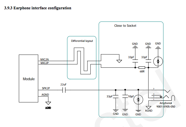
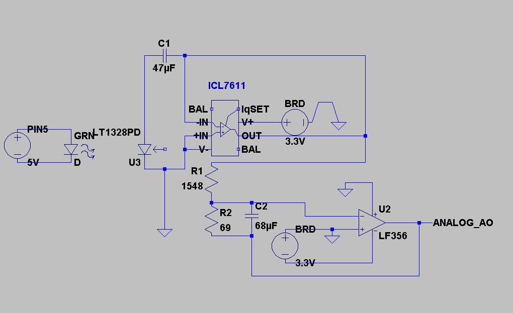
Powering an Arduino and the GSM shield from a USB connection is not recommended, as USB cannot provide the required current for when the modem is in heavy use. The modem can pull up to 2A of current at peak usage, which can occur during data transmission. This current is provided through the large orange capacitor on the board`s surface. The shield supports AIN1 and AOUT1 as audio interfaces; an analog input channel and an analog output channel.
The input, exposed on pins MIC1P/MIC1N, can be used for both microphone and line inputs. An electret microphone can be used for this interface. The output, exposed as lines SPK1P/SPK1N, can be used with either a receiver or speaker. Through the modem, it is possible to make voice calls. In order to speak to and hear the other party, you will need to add a speaker and microphone. There are two small buttons on the shield. The button labeled "Reset" is tied to the Arduino reset pin. When pressed, it will restart the sketch. The button labeled "Power" is connected to the modem and will power the modem on and off. For early versions of the shield, it was necessary to press the power button to turn on the modem. Newer versions of the board will turn the modem on automatically. If you have an early version of the shield, and it does not turn on automatically, you can solder a jumper to the CTRL/D7 pad on the reverse side of the board, and it will turn on when an attached Arduino receives power. Several of the modem pins are exposed on the underside of the board. These provide access to the modem for features like speaker output and microphone input. See the datasheet for complete information. 🔗 External reference
Related Circuits
The code implementation discussed in the previous post has been initiated. To improve organization, the code has been modularized into functions, simplifying the overall structure. It is available along with the other code. Challenges were encountered in calculating averages...
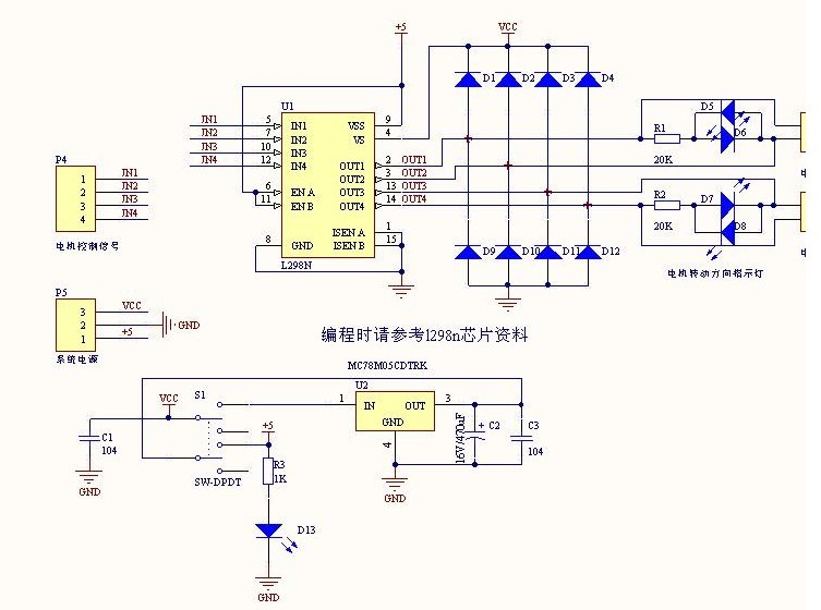
The L298N driver module incorporates the ST L298N chip, commonly utilized to drive two DC motors with voltage ratings between 3V and 30V. It features a 5V output interface that provides power for 5V single-chip circuitry and supports 3.3V...
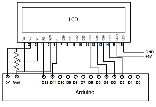
To achieve this, the first step involves establishing the necessary physical connections between the Arduino board and the LCD. Following this, code must be written to display the desired text on the LCD. LCDs have become the standard means...
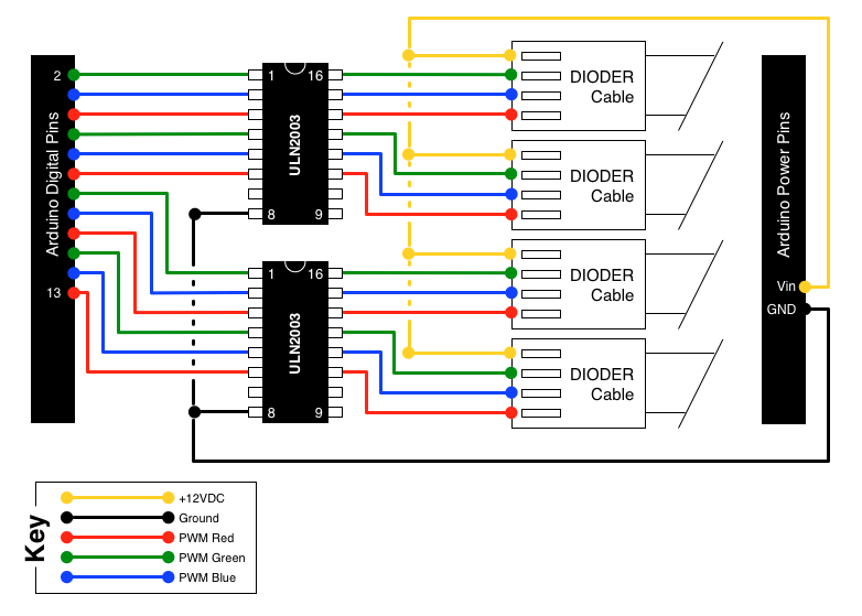
A few weeks ago, it was noted that IKEA offers a set of color-changeable LED strips. There has been a search for an effective method to provide... The color-changeable LED strips from IKEA are designed to offer flexibility in lighting...
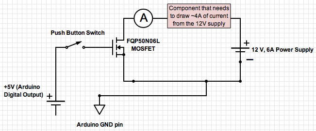
If the ground of the Arduino is disconnected from the negative terminal of the power supply, current flows through the MOSFET, even when the switch is not closed. In an electronic circuit involving an Arduino and a MOSFET, maintaining a...
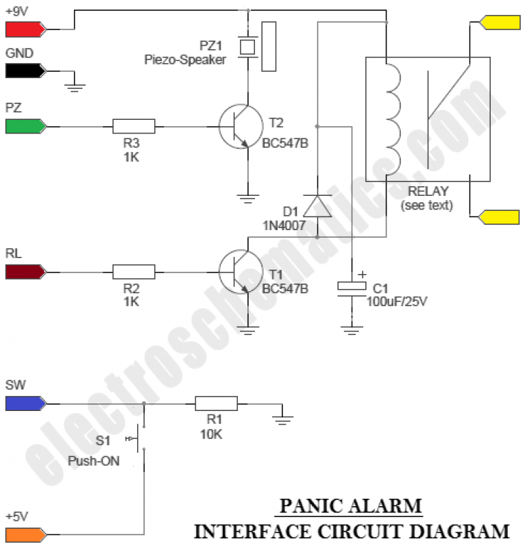
The circuit is an Arduino-based Panic Alarm. The wiring is straightforward, enabling even novices to construct this interesting circuit with ease. Arduino is a family of microcontrollers and a software environment (Arduino IDE) that facilitates the creation of programs,...