
arduino knight rider

The Knight Rider LED display emulates the iconic light sequence from the television series, where a series of LEDs light up in a moving pattern. This project is ideal for beginners as it introduces fundamental concepts of electronics, programming, and circuit assembly.
The circuit typically consists of an Arduino Uno microcontroller, several LEDs, resistors, and a breadboard for assembly. The LEDs are arranged in a linear fashion, simulating the effect of a moving light. Each LED is connected to a digital output pin on the Arduino through a current-limiting resistor, which is essential to prevent excessive current from damaging the LEDs.
To implement the project, the following components are required:
- Arduino Uno board
- Breadboard
- 10 LEDs (preferably in a single color for uniformity)
- 10 resistors (220 ohms or 330 ohms, depending on the LED specifications)
- Jumper wires for connections
- A USB cable for programming the Arduino
The basic circuit design involves connecting the anode (longer leg) of each LED to a separate digital pin on the Arduino, while the cathode (shorter leg) is connected to the ground through a resistor. The Arduino is programmed to turn on and off each LED in sequence, creating the visual effect of a moving light.
The programming aspect involves writing a simple sketch in the Arduino IDE that defines the sequence in which the LEDs will light up. The delay function can be used to control the speed of the light movement. This project not only enhances understanding of basic circuit connections but also provides practical experience in coding and debugging Arduino programs.
In summary, the Knight Rider LED display project is an excellent starting point for those new to electronics, offering hands-on experience with both hardware and software components in a fun and engaging manner.Build a Knight Rider LED display on breadboard controller by an Arduino. An easy circuit for beginners in electronics using an Arduino Uno.. 🔗 External reference
Related Circuits
A custom Lo-fi Arduino Guitar Pedal has been developed, utilizing a repurposed enclosure and twisted pair converters. Currently, it features a single output, with potential for future expansion. The design includes a digital delay effect, which was initially intended...
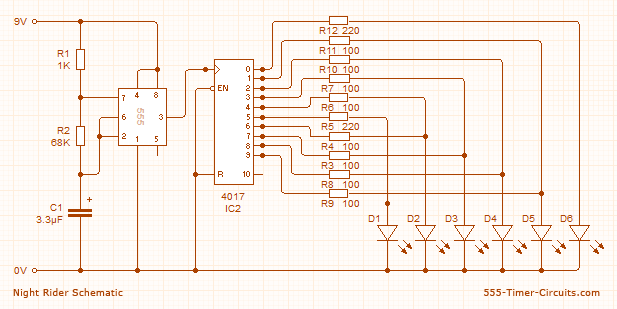
In the Knight Rider circuit, the 555 timer is configured as an oscillator in astable mode. The output from the 555 timer is connected directly to the input of a 4017 decade counter, specifically to its CLOCK line. The...
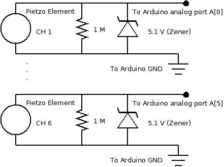
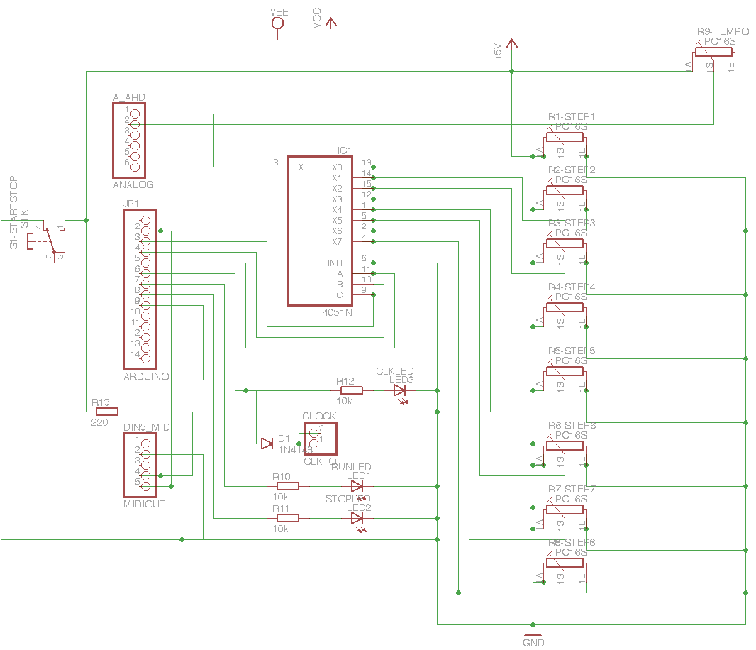
The piezo element is connected solely to Channel 1 (Arduino A[0] port). Channels 1 through 6 are linked to female mono jacks, with the ground (GND) wiring arranged in series from jacks 1, 2, and 3, continuing to the...
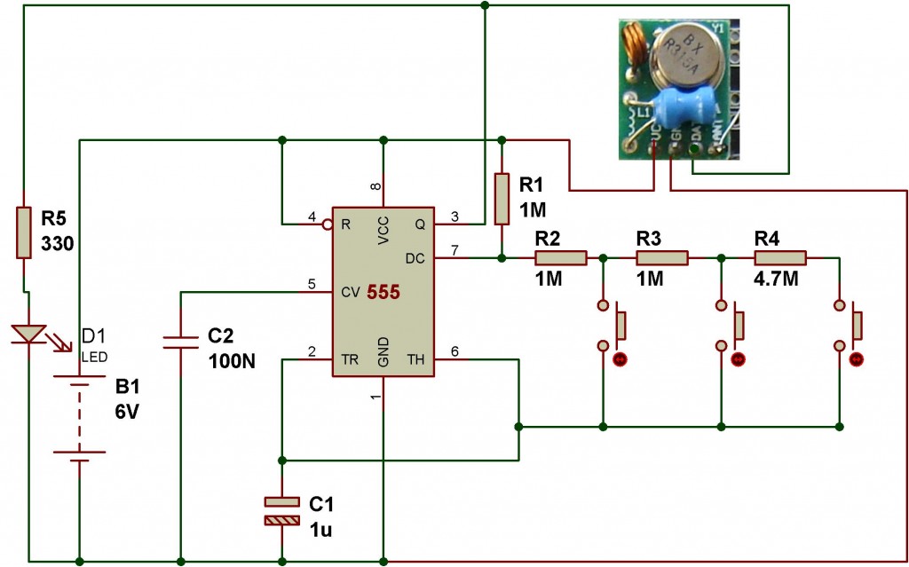
This wireless transmitter and receiver pair operates at 315 MHz. They can easily fit into a breadboard and work well with microcontrollers to create a simple wireless data link. As these are only transmitters, they will only facilitate one-way...
An intervalometer for the Canon 400D camera has been developed. This device is based on an Arduino platform and utilizes code adapted from the creator of the Intervaluino project. The intervalometer is a specialized electronic device designed to automate the...
Charge a simple servo that only has + and - pins. Typically, the - pin is connected to ground, while the + pin is connected to a digital output from an Arduino. This setup works, but the servo operates...