
Knight Rider Circuit

The circuit utilizes six 3mm red LEDs, which can be arranged at the front of a model car to create a realistic lighting effect. Additionally, the outputs can be interfaced with driver transistors to control a larger display. The overall circuit draws 22mA, with each LED receiving around 7mA. The outputs interact through the 100Ω resistors, except for Q0 and Q5, which do not interfere with each other. The parts list includes: 1 NE555 bipolar timer, 6 red LEDs, 8 resistors of 100Ω (1/4W), 2 resistors of 220Ω (1/4W), 1 resistor of 1KΩ (1/4W), 1 resistor of 68KΩ (1/4W), 1 electrolytic capacitor of 3.3µF (16V), 1 4017 decade counter, and 1 9V battery.
The Knight Rider circuit is an example of a simple yet effective electronic design that employs a 555 timer to generate a clock signal for the 4017 decade counter. The astable configuration of the 555 timer allows it to continuously oscillate, producing a square wave output that serves as the clock input for the 4017. This setup results in the sequential activation of the decade counter's outputs, which can be visually represented by the LEDs.
To ensure proper operation and prevent damage to the LEDs, it is critical to include current-limiting resistors. The choice of 100Ω or 220Ω resistors depends on the desired brightness of the LEDs and the available supply voltage. The interaction between the outputs is managed through these resistors, which help to balance the current distribution among the LEDs.
In applications where a larger display is required, the outputs from the 4017 can be connected to transistors that act as switches, allowing for higher current loads and more substantial lighting effects. This versatility makes the Knight Rider circuit suitable for various projects, including model cars and other decorative electronic displays.
The components listed in the parts list are readily available and can be sourced from most electronics suppliers. The design is straightforward, making it an excellent choice for hobbyists and those looking to learn about basic electronic principles, including oscillators, counters, and LED driving techniques.In the Knight Rider circuit, the 555 is wired as an oscillator (Astable mode). The output of the 555 is directly connected to the input of a 4017 decade counter. The input of the 4017 counter is called the CLOCK line. The 10 outputs Q0 to Q9 become active, one at a time, on the rising edge of the waveform from the 555. Each output can deliver about 20mA but a LED should not be connected to the output without a current-limiting resistor (100R or 220R).
Using six 3mm LEDs, the display can be placed in the front of a model car to give a very realistic effect. The same outputs can be taken to driver transistors to produce a larger version of the display. This circuit consumes 22mA while only delivering 7mA to each LED. The outputs are “fighting“ each other via the 100R resistors (except outputs Q0 and Q5). Parts list ::: 1x NE555 Bipolar Timer 6x LED (Red) 8x 100 Resistor (1/4W) 2x 220 Resistor (1/4W) 1x 1K Resistor (1/4W) 1x 68K Resistor (1/4W) 1x 3.3µF Electrolytic Capacitor (16V) 1x 4017 Decoded Decade Counter 1x 9V Voltage battery ....
🔗 External reference
Related Circuits
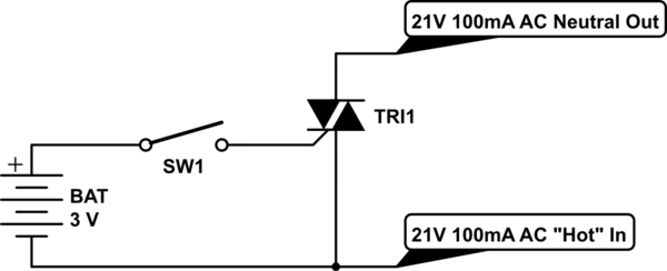
Control a furnace using a 3.3V microcontroller. The furnace operates by connecting a common 21V AC "hot" line to one of two AC "neutral" output lines: Fan and Heat. When connected, they have relatively low current flow, approximately 100mA....
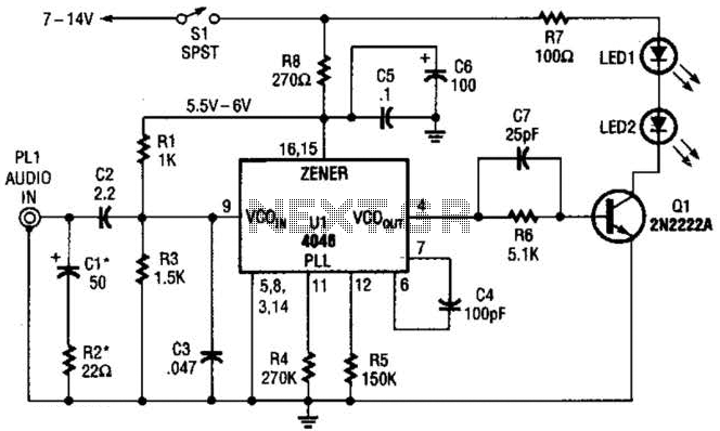
The transmitter for the wireless headphones is constructed using a CD4046 CMOS phase-locked loop, which is paired with a driver transistor and a set of infrared LEDs. While the CD4046 contains two phase comparators, a voltage-controlled oscillator (VCO), a...
The circuit is a DC to DC converter utilizing a standard 12 VAC center-tapped power transformer configured as a blocking oscillator. Although the circuit exhibits low efficiency, it generates a high voltage suitable for low-power applications. The input battery...
D1 (Schottky diode) and C2 form a rectifier to create DC voltage from the Joule Thief. A Zener diode D2 is included to limit the voltage to 5.1V, preventing damage to the microcontroller, which has a maximum voltage tolerance...
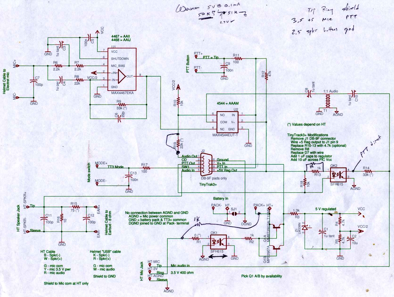
Connect the Byonics TinyTrak 3+ GPS modem, helmet earbud/mic, and external battery pack to the Z-1A, which is incompatible with the Wouxun. The KG-UV3D utilizes the Kenwood HT interface with a single ground for mic, speaker, and PTT functions,...

The circuit utilizes a 555 timer IC to create a lighting group delay effect, as illustrated in Figure 2-46. It consists of the 555 IC along with a resistor and capacitor configuration that establishes the delay. The circuit remains...