
High Voltage Converter: 90V From 1.5V

The described circuit utilizes the LT1073 switching regulator, which is a highly efficient device for stepping up low input voltages to higher levels. In this configuration, the input voltage of 1.5V is boosted to 90V, making it suitable for applications requiring high voltage from low power sources. The operation of the circuit is centered around the switching transistor that engages in rapid on-off cycles, allowing for the energy storage in the choke (inductor) L1.
When the transistor is activated, it connects L1 to ground, allowing current to flow through it and creating a magnetic field. The energy stored in this magnetic field is released when the transistor turns off, inducing a voltage spike that forward-biases diode D1. This spike charges capacitor C3, which serves as an energy reservoir.
The cascading arrangement of diodes (D1, D2, D3) and capacitors (C2, C3, C4) forms a voltage multiplier. Each diode conducts during the charging cycle, and the capacitors store charge, effectively increasing the voltage output. The design ensures that the output voltage is quadrupled due to the series and parallel arrangement of these components.
The resistors forming the potential divider play a critical role in regulating the output voltage by providing feedback to the control loop of the LT1073. The selection of high-precision, low-tolerance metal film resistors is vital for maintaining stable operation and ensuring that the output voltage remains at 90V under varying load conditions.
The use of fast recovery diodes, such as the MUR120, is essential to handle the high reverse voltages without significant losses, thereby improving the efficiency of the circuit. The choke selected, Coilcraft DO1608C-154, is designed to handle the required current and voltage levels, ensuring reliable performance.
Overall, this circuit design is effective for applications requiring a compact solution for generating high voltages from low power sources, capable of delivering several milliamps of current for various electronic applications.The circuit shows one way of obtaining a voltage of 90V from a 1. 5V battery supply. The LT1073 switching regulator from Linear Technology ( operates in boost mode and can work with an input voltage as low as 1. 0 V. The switching transistor, which is hidden behind connections SW1 and SW2, briefly takes one end of choke L1 to ground.
A magnetic fiel d builds up in the choke, which collapses when the transistor stops conducting: this produces a current in diode D1 which charges C3. The diode cascade comprising D1, D2, D3, C2, C3 and C4 multiplies the output voltage of the regulator by four, the pumping of C2 causing the voltage developed across C4 via C3, D2 and D3 to rise.
Finally, the regulator control loop is closed via the potential divider (10 M and 24 k). These resistors should be 1 % tolerance metal film types. With the given component values, fast diodes with a reverse voltage of 200 V (for example type MUR120 from On Semiconductor and a choke such as the Coilcraft DO1608C-154 ( an output voltage of 90 V will be obtained. The output of the circuit can deliver a few milliamps of current. 🔗 External reference
Related Circuits
With a 1.5V battery supply, the integrated circuit LM3909 can drive the light-emitting diode NSL5027. The 300μF electrolytic capacitor acts as a timing capacitor, which limits the flash speed to approximately 1Hz. The circuit utilizes the LM3909, a popular LED...
A tone control circuit is an electronic circuit designed to manipulate the tone of an audio signal. The tone of an audio signal is analogous to color in light. The tone control circuit typically consists of various components such as...
Many RC oscillators utilize an advanced circuit in the phase shift unit. This configuration employs a voltage feedback amplifier, which experiences a significant decline in gain at higher frequencies, leading to the cessation of oscillation before achieving the desired...
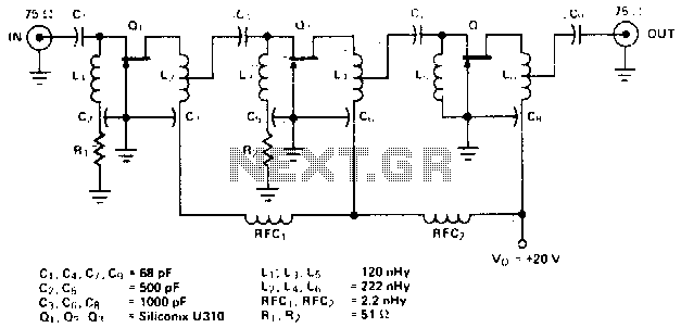
The amplifier circuit is designed for a center frequency of 225 MHz, with a bandwidth of 50 MHz at 1 dB, low input voltage standing wave ratio (VSWR) in a 75-ohm system, and a gain of 24 dB. Three...
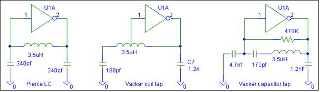
This oscillator does not require biasing components. Only an inductor and various matching or tuning capacitors are needed to set the operating frequency. The active component is the 74HCU04 hex inverter, with only one of the six inverters necessary...
In a hybrid system, an analog system with digital control, voltage-controlled components are crucial as they can be interfaced with a Digital-to-Analog Converter (DAC) from the digital system. In hybrid systems, the integration of analog and digital components allows...