
Arduino Vocal Effects Box Schematic

The audio output circuit typically involves several key components that work together to process and deliver sound signals. The primary elements include an audio source, an amplifier, and the output transducer, such as a speaker or headphone jack.
The audio source could be a microcontroller, a digital signal processor, or any device capable of generating audio signals. This source feeds the audio signal into an amplifier, which increases the signal's power to drive the output transducer effectively. The amplifier may be a class A, B, or D type, depending on the power efficiency and fidelity required for the application.
In the schematic, the audio output circuit may also feature capacitors and resistors for filtering and impedance matching. Capacitors are often used to block DC components while allowing AC audio signals to pass through, ensuring that only the intended audio frequencies are amplified. Resistors can help set the gain of the amplifier and provide stability to the circuit.
Moreover, the output stage may include protection circuits to prevent damage from overcurrent or voltage spikes, ensuring reliable operation. This can involve the use of diodes or fuses that safeguard the circuit.
Overall, the design of the audio output circuit is crucial for achieving high-quality sound reproduction, making it a fundamental aspect of audio electronics projects.I`ve broken the schematic into three parts so it is easier to understand. The first schematic shows the audio out circuit. This project outputs audio.. 🔗 External reference
Related Circuits
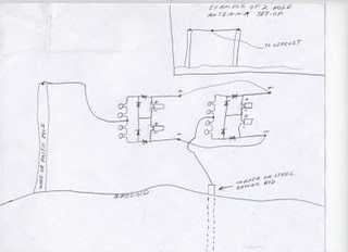
If you decide to use 2 circuits, I just connect their outputs together...neg output from first circuit to neg output of second circuit & pos output from first circuit to pos output of second circuit. And take readings from...
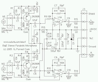
The mini condenser microphone converts sounds into an electrical signal. Resistor R1 provides bias for the condenser microphone's internal amplifier transistor. The 2N3906 PNP transistor acts as a low-noise microphone input amplifier. The 10K gain potentiometer is used for...
The combination of the LM4651 driver IC and the LM4652 power MOSFET Class D power amplifier IC provides a high-efficiency amplifier solution, suitable for self-powered speakers, subwoofers, and quality car boosters. The LM4651 is a fully integrated conventional pulse...

In forward inverter system applications, the IRZ110 is used to receive a signal when the line is shown in Figure 12-39. In this application, the next channel utilizes the IR 2110 and shares an input pulse signal that determines...
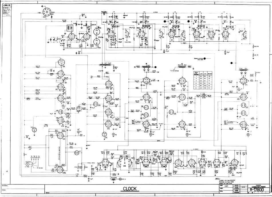
A hard copy schematic diagram related to the computer CSIRAC. The schematic diagram illustrates the detailed connections between all components in the circuit. It is used for building the circuit and later for testing. For CSIRAC, the most common...
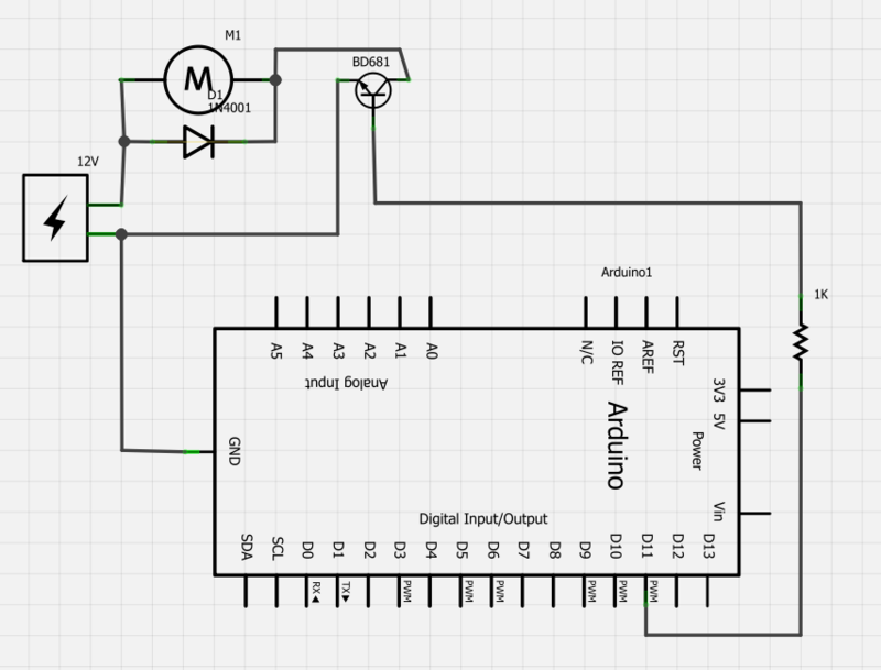
Power a 12V fan using a Darlington transistor to control the speed from an Arduino. When wired as described, nothing happens even though a PWM signal is being sent. It is suggested to edit the question and ensure the...