
Free energy Schematic II

The circuit design involves two identical circuits whose outputs are connected in parallel, facilitating a combined output. The negative output from the first circuit is connected to the negative output of the second circuit, while the positive output from the first circuit connects to the positive output of the second circuit. This configuration allows for simultaneous readings from a common point, which is the junction where the two circuits are interconnected.
A ground wire is taken from the circuit, specifically positioned between two large electrolytic capacitors, ensuring a stable reference point for the circuit's operation. The use of two 100 microfarads polarized electrolytic capacitors provides significant filtering and stabilization of the power supply, which is crucial for maintaining the performance of the circuit.
The circuit also incorporates four ceramic disk capacitors rated at 0.1 microfarads. These capacitors serve as high-frequency bypass components, effectively filtering out noise and ensuring stable operation across the circuit's frequency range.
Four germanium diodes, specifically the 1N34A type, are utilized in the design. These diodes are known for their low forward voltage drop and are suitable for applications requiring high sensitivity. The 1N34A diodes have a peak reverse voltage rating of 75 volts, making them appropriate for various low-power applications. When selecting diodes, it is essential to verify their specifications to ensure compatibility with the intended circuit design.
For sourcing components, the diodes can be found at Mouser Electronics, which provides a reliable supply. Additional resources, such as datasheets and specifications, are available online to assist in confirming the characteristics of the 1N34A diodes and comparing them with other types of germanium diodes. Proper selection and implementation of these components are critical to achieving the desired performance and reliability of the overall circuit.If you decide to use 2 circuits, i just connect their outputs together...neg output from first circuit to neg output of second circuit & pos output from first circuit to pos output of second circuit. And take readings from same place....from where you conected the 2 circuits together. Ground wire connects off of circuit, from inbetween 2 large electrolytic capacitors. 4) .1 micro Farads ceramic disk capacitors 2) 100. micro Farads electrolytic polorized capacitors 4) germanium diodes (1N34A)(mouser# 526-1N34A) diodes can be found here at mouser, these are the one that i use..... http://www.mouser.com/Search/Refine.aspx?Keyword=1n34 i see that there are a few types of germanium diodes out there, the ones i get from mouser are rated at Peek Reverse Voltage 75V here is another website that has good picture of them...but not sure if they are exactly the same ratings.
https://www.micro-tools.com/store/item_detail.aspx?ItemCode=1N34A here is a website that has specifications on some of the differant types... http://www.datasheetcatalog.com/datasheets_pdf/1/N/3/4/1N34A.shtml 🔗 External reference
Related Circuits

After extensive searching online, a 16-step sequencer schematic was not found that did not require an Arduino, PIC, or another digital controller. A simple 3-chip analog 16-step sequencer with variable speed and arpeggio has been developed, drawing from various...
For capacitor C3, a 100pF capacitor is placed across resistor R2. The circuit functions similarly to previous configurations, although no explanation is provided. The purpose of this component may be self-evident to experienced users, but it may not be...
Electronic circuits are presented in schematic form. A schematic is essentially a map that illustrates the path of current through various components. Each component is represented by a symbol, typically accompanied by a label or a value, or both....
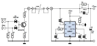
This circuit was designed to transmit commands over an LNB coaxial cable. An LNB (Low-Noise Block downconverter) is commonly used for satellite TV reception and is positioned at the focal point of a satellite dish. The circuit generates a...
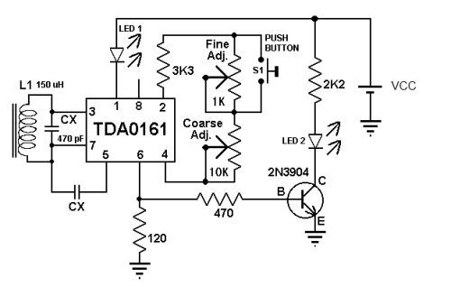
This metal detector circuit diagram utilizes the TDA0161 monolithic integrated circuit, which is designed to detect metallic objects by measuring variations in high-frequency Eddy current losses. The output signal is influenced by changes in supply current, which varies based...

In the project, the LCD data ports are connected to port 1 of the controller, while the control pins, namely RS, E, and R/W, are connected to pins 3, 5, 6, and 2, 1 of the controller. The LCD...