
transistors Having difficulties using a darlington (BD681) to drive a 12V fan from an Arduino
 to drive a 12V fan from an Arduino")
To power a 12V fan using a Darlington transistor for speed control via an Arduino, the following circuit configuration is advised. The Darlington transistor, which consists of two bipolar junction transistors (BJTs) connected together, provides high current gain and is suitable for switching applications.
The circuit should include an NPN Darlington transistor, such as the TIP120, which is capable of handling the required current for the fan. The Arduino will output a PWM signal to control the fan speed. Connect one of the PWM-capable digital pins of the Arduino (for example, pin 9) to the base of the Darlington transistor through a current-limiting resistor (typically 1kΩ). This resistor is essential to protect the Arduino from excess current.
The collector of the Darlington transistor should be connected to the positive terminal of the 12V power supply, while the emitter connects to one terminal of the fan. The other terminal of the fan should be connected to the ground of the power supply. It is crucial to ensure that the ground of the Arduino is also connected to the ground of the 12V power supply to establish a common reference point.
For additional protection, a flyback diode (e.g., 1N4001) should be placed in parallel with the fan terminals to prevent back EMF generated by the inductive load when the fan is switched off. The cathode of the diode connects to the positive terminal of the fan, while the anode connects to the ground side.
In summary, the circuit consists of an Arduino sending a PWM signal to a resistor connected to the base of a Darlington transistor, which in turn controls the fan powered by a 12V supply. Proper connections and component selection are critical to ensure functionality and prevent damage to the components.Power a 12v fan using a darlington so I can control the speed from an Arduino. When I wire up as below nothing happens, even though I`m sending a PWM signal: Please draw a proper circuit. Edit your question and hit Ctrl+M, the current image is unreadable. Check your breadboard, most rows along the side are have one or two interruptio ns half way (Arduino`s GND connection). Possibly add a picture of your setup aswell. jippie Apr 13 `13 at 20:16 🔗 External reference
Related Circuits

A control program typically requires more than simply turning outputs on and off; these actions are triggered by events. Such events are connected to the input of a microcontroller, which determines the subsequent actions. Inputs can originate from various...
The 1N4001 is a 1 Amp silicon rectifier with a voltage range of 50 to 1000 volts. It features guaranteed high-temperature soldering, high current capability, a diffused junction, low reverse leakage, and utilizes a void-free molded plastic technique for...
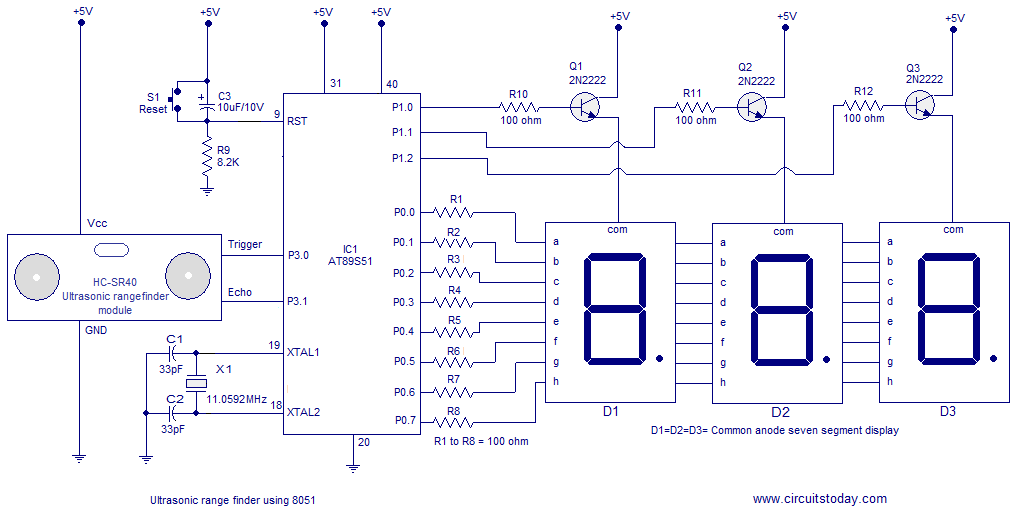
A simple ultrasonic range finder using the 8051 microcontroller is presented in this article. This ultrasonic rangefinder can measure distances up to 2.5 meters with an accuracy of 1 centimeter. The AT89S51 microcontroller and the ultrasonic transducer module HC-SR04...
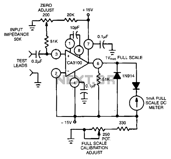
This circuit utilizes the CA3100 BiMOS operational amplifier to drive a 1-mA meter movement to its full scale with a 1-V RMS input. The circuit configuration incorporates the CA3100 BiMOS operational amplifier, which is known for its high input impedance...
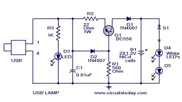
A simple USB LED lamp circuit utilizing a 5-volt power supply sourced from a USB port, designed to illuminate a desktop or laptop computer during power outages. The USB LED lamp circuit operates by converting the 5-volt DC power provided...
Battery eliminators are circuits that create a DC power supply from AC mains. Essentially, battery eliminator circuits consist of a step-down transformer, rectifier, and voltage regulator. A simple circuit of a multipurpose battery eliminator features various output voltage ranges...