
100W Inverter Circuit

The 100 Watt inverter circuit is an efficient solution for converting DC power to AC power using a straightforward design. At the heart of the circuit is the CD4047 IC, which serves as the pulse generator. It is configured in astable mode, meaning it continuously oscillates without requiring any external triggering. This configuration allows it to produce two square wave outputs that are 180 degrees out of phase, essential for driving the push-pull configuration of the transistors effectively.
The four 2N3055 transistors are arranged in a push-pull configuration, which enables them to alternate in switching the load on and off, thereby generating the desired AC output. Each transistor is capable of handling significant current and power, making them suitable for this application. When one transistor is turned on, the other is turned off, ensuring that the load receives alternating current.
To further enhance the performance of the inverter, appropriate biasing resistors are used to control the base current of the 2N3055 transistors, ensuring they operate efficiently within their specified limits. Additionally, a transformer may be employed at the output stage to step up the voltage to the desired level for the load, depending on the application requirements.
Overall, this inverter circuit is a practical example of using a minimal component count to achieve effective power conversion, making it suitable for various applications where AC power is needed from a DC source. Proper attention to component ratings and circuit layout will ensure reliable operation and longevity of the inverter system.Here is a 100 Watt inverter circuit using minimum number of components. Here we use CD 4047 IC from Texas Instruments for generating the 100 Hz pulses and four 2N3055 transistors for driving the load. The IC1 Cd4047 wired as an astable multivibrator produces two 180 degree out of phase 100 Hz pulse trains..
🔗 External reference
Related Circuits
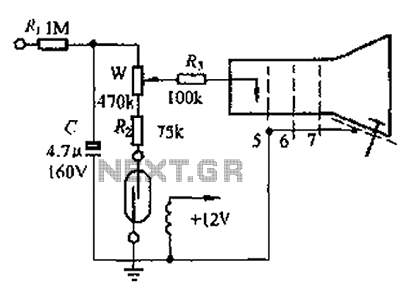
A reed switch is utilized in a TV highlights cancellation circuit. A brightness potentiometer is grounded in series with the reed switch. Under normal operation, the reed contact remains closed, allowing the capacitor C to charge to approximately 160V....
This circuit when used with a 555 timer will cause light emitting diodes to turn on and off more slowly. This will make the LEDs appear similar to incandescent lamps. The described circuit utilizes a 555 timer IC configured in...
When the unit is positioned near a live conductor, whether insulated or buried in plaster, capacitive coupling occurs between the live conductor and the probe. This interaction activates the counter, resulting in the LED flashing five times per second,...
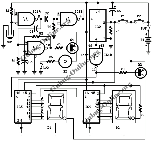
This design features a signal logic tester that utilizes a common cathode seven-segment display. The display indicates a logic level "1" (represented by an "H" on the display) or a logic level "0" (represented by an "L" on the...
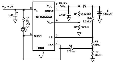
NiMH charger circuit diagram using ADM66A. Related searches include charger circuit, NiMH charger circuit, lead acid battery charger circuit, LiPo charger circuit, automatic battery charger circuit, simple battery charger circuit, lithium battery charger circuit, charger circuit diagram, and 12V...
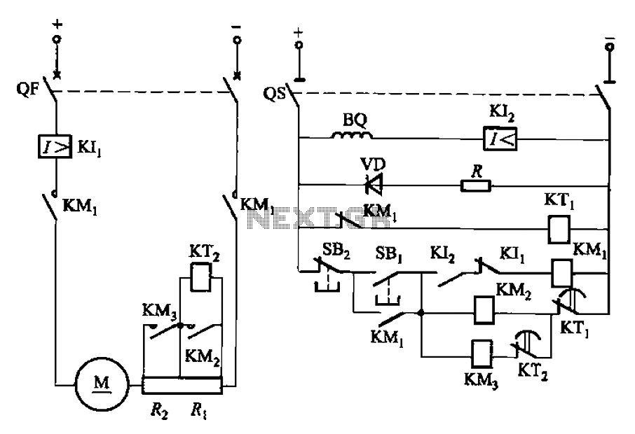
The circuit illustrated in Figure 3-191 features a DC motor armature circuit that includes two series startup resistors, Ri and Rz. The operation of the motor is controlled using buttons for starting and stopping. During the startup phase, two...