
Asia ultrasonic remote control fan speed control circuit diagram

The described circuit employs an ultrasonic remote control mechanism for fan operation, allowing for seamless integration into home automation systems. The ultrasonic transmitter emits signals that are omnidirectional, enhancing the usability of the remote control. The piezoelectric buzzer (V1) acts as a receiver, converting ultrasonic waves into electrical signals. The inclusion of an inductor (L) and capacitor (C4) forms a tuned circuit that filters the incoming signal to the desired frequency, ensuring reliable operation.
Once the signal is processed, it is amplified by transistor V2, which ultimately generates a pulse output. This pulse serves as a trigger for the CD4017 decimal counter, a versatile component known for its ability to count up to ten inputs. The outputs Q1, Q2, and Q3 are sequentially activated based on the count, allowing for precise control over the connected devices. When the fourth pulse is received, the counter resets, readying the system for the next cycle of operation.
The integration of a transistor to drive relays is a critical aspect of the design, enabling the control of higher power devices such as fans. The relay contacts are configured to adjust the speed of the fan via a governor, which modulates the power supplied to the fan motor based on the control signals received.
This circuit can be further expanded to support up to nine channels, providing a scalable solution for controlling multiple fans or other devices within a household. Such modifications would involve additional relays and possibly a more complex control logic to manage the increased number of outputs effectively. Overall, this design exemplifies a robust approach to remote control applications in home environments, leveraging ultrasonic technology for enhanced functionality.Fans can achieve remote control switch, speed control, remote control can also be achieved in other household switches. Its main feature is the use of sub-transmission side ult rasonic transmitter, no direction restriction, without power, and durability. Asia ultrasonic signal received by the piezoelectric buzzer V1 amplification, L, C4 frequency selection, and then amplified by V2, and the output pulse. Each operation, pinching at the transmitter, V2 collector outputs a positive pulse trigger signal, the decimal counter CD4017 count.
Use CD4017s Q1, Q2, Q3 gear. When the fourth signal arrives, IC cleared. IC control transistor driven relays. Speed relay coil contacts to the former governor to change the fan speed. Slightly modified circuit can be expanded to 9 road.
Related Circuits
The circuit includes a momentary switch S1 that triggers an alarm pulse for the decade counter IC2, which increments its count with each alternating alarm pulse or the activation of switch S1. Ten variable resistors (VR1 through VR10) are...
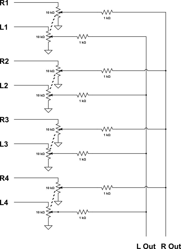
This audio mixer combines multiple audio inputs into a single audio output, equipped with knobs to adjust the volume for each channel. The specific build includes... The audio mixer is designed to facilitate the blending of various audio signals, allowing...
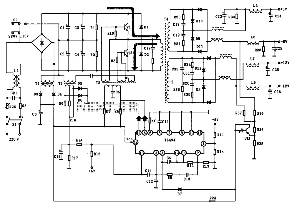
The BE-150 mainframe computer features a switching power supply circuit. The circuit utilizes the oscillation control IC TIA94. A 22V voltage is supplied through the power switch S1, fuse, filter capacitor C21, L2, and a mutual inductance filter, which...
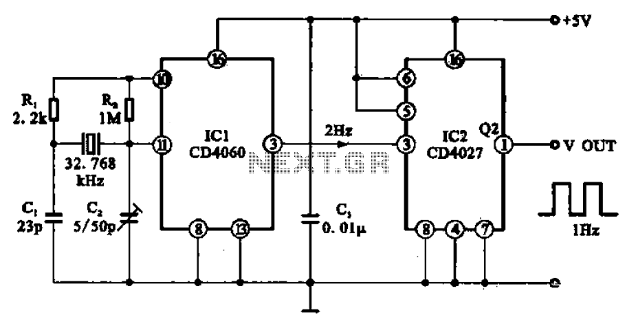
A 1Hz clock signal generator circuit is presented, which demonstrates a sophisticated clock signal generating mechanism. This circuit can be utilized for digital clocks and timing applications. It comprises a binary counter (CD4060), a JK flip-flop (CD4027), and a...
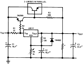
The following circuit diagram illustrates the application of the LM117 as a high current adjustable regulator. The LM117 is capable of supplying more than 1.5A. The LM117 is a popular adjustable voltage regulator that is designed to provide a stable...
The schematic diagram below illustrates a typical 1.5V flasher circuit using the LM3909. The LM3909 is a monolithic oscillator designed specifically for flashing Light Emitting Diodes (LEDs). The LM3909 flasher circuit operates at a low voltage of 1.5V, making it...