
BE-150 mainframe computer switching power supply circuit

The BE-150 mainframe computer's switching power supply circuit is designed to convert and regulate electrical power efficiently. The circuit begins with a 22V input, which is routed through the power switch S1 and a fuse for protection against overcurrent. Following this, the input passes through a filter capacitor (C21) and an inductor (L2), which together help to smooth out voltage fluctuations and reduce ripple.
The rectification process is performed by a bridge rectifier, transforming the AC voltage into a stable 30V DC output. This voltage is then utilized to power the switching transistors VT1 and VT2. The oscillation control IC TIA94 plays a crucial role in generating the necessary control signals. The output from TIA94 is an oscillation signal that is transmitted to the base of the transistors via transformer T2, which serves as a coupling element.
Transistors VT1 and VT2 amplify the switching pulses, which are then applied to the primary winding of transformer T4. The transformer T4 is vital for voltage transformation and isolation between the primary and secondary circuits. The secondary winding of T4 provides rectified and filtered outputs, yielding multiple DC voltage levels, specifically +5V and +12V, which are essential for powering various components of the mainframe computer.
Additionally, components Tl and I2 are responsible for generating a start signal during the boot process, ensuring that the circuit initializes correctly. The operation of T2 is essential for maintaining the oscillator signal, enabling continuous operation of the power supply circuit. This design allows for a reliable and efficient power management solution tailored for the BE-150 mainframe computer, ensuring stable operation under varying load conditions. BE-150 mainframe computer switching power supply circuit The host computer is shown in BE-150-type switching power supply circuit, the oscillation control IC to switch TIA94. A C 22V voltage through the power supply switch S1, fuse, filter capacitor C21, L2 and mutual inductance filter rectifier bridge rectifier heap to 30V DC for the switch VT1, VT2 provide voltage. IC TIA94, foot switch output oscillation signal, the transformer T2 for the switch VT1, VI2 base providing a driving pulse, switching pulse by VT1, VT2 after amplification applied to the transformer primary T4, T4 of the secondary rectified, filtered multiple sets of output DC voltage +5 V, + 12 V.
Tl, I2 formation start signal at boot time, the pros and cons of T2 after work provided to maintain the oscillator signal fed windings.
Related Circuits
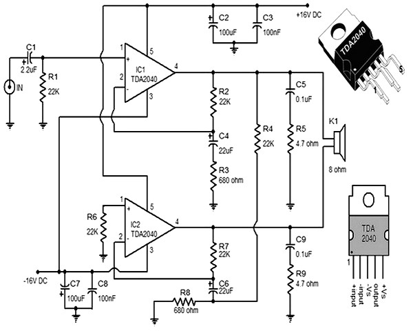
This small and compact stereo amplifier is powerful and can easily replace a broken amplifier or be used in new constructions, or to create an active speaker, when combined with a preamplifier. Its remarkable features make it a true...
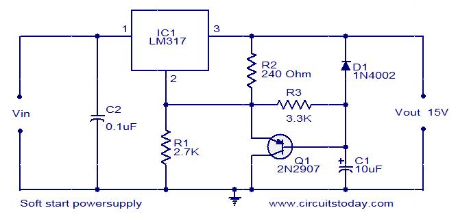
This post presents an interesting topic about switching power supply circuit diagrams for those who wish to learn more. A switching power supply is a type of power supply that uses a switching regulator to convert electrical power efficiently. Unlike...
These two tank circuits appear to broaden the operating spectrum. The accompanying information sheet indicates that when both circuit stages oscillate at the same frequency, the power output reaches its maximum. This suggests that if the tunable tank circuit...
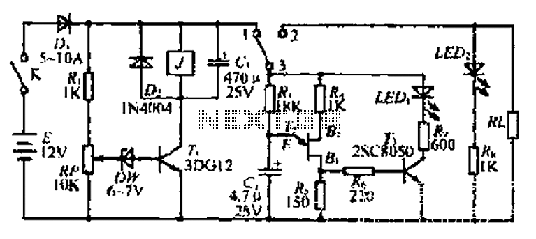
The discharge control circuit consists of a battery management system designed to prevent over-discharge of a battery. It features a relay control mechanism that activates when the battery voltage drops below a specified threshold of approximately 10.5V. The circuit...
This application note provides a concise overview of power amplifier theory and presents simulation results that offer insights into the operation of the power amplifier across all of MAXIM's LFRF transmitters and transceivers. Power amplifiers are critical components in communication...
You may be familiar with this effect. You switch audio equipment such as an amplifier to a different input and there is a loud click or "thump" in the speaker system. Not all equipment is affected. Some high-end audio...